
General information
The main purpose of the toothed belt / chain is to drive the timing mechanism (timing), while it provides coordinated opening / closing of valves, depending on the current stroke of the working cycle in each of the engine cylinders. In addition, on various engine models, some auxiliary units, such as high-pressure fuel pumps, are driven by means of a toothed belt / chain (diesel models), water pump and some other units.
Inspection and replacement of the toothed belt must be carried out in strict accordance with the Maintenance Schedule (see chapter 1). Whistling and howling of the toothed belt when the engine is running indicates its excessively strong tension, with a weak tension, the belt hits the cover. Timing belt failure can cause severe engine damage, so it is recommended to replace the belt each time it is removed. If you plan to reuse the belt, before removing its gears, mark with a marker (in the form of an arrow) to determine the direction of rotation during subsequent installation. Note: The belt rotates clockwise when looking at the engine from the belt drive side. Before removing the belt, it is recommended to draw a diagram of its tension.
The chain requires virtually no maintenance during its entire service life. When troubleshooting or replacing chain driven units, it may be necessary to remove and sometimes replace the chain. After each removal of the chain, the valve timing must be adjusted. These operations can only be performed using special tools - take care of purchasing them in advance.
During operation, as a result of weakening the belt / chain, increasing the length, or with some damage to the belt, he / she can jump one or more teeth on the gears / camshaft sprockets, which will lead to a violation of the valve timing, a decrease in engine efficiency, and in in some cases to failure of valves or pistons of cylinders. The valve timing is adjusted with the toothed belt / chain removed by aligning the marks / installing devices when setting the TDC position for the corresponding piston (see Section 6).
Attention: When turning the camshafts with the toothed belt/chain removed, none of the pistons must be in the TDC position - otherwise the valves will rest against the piston, which may damage the valves and / or pistons. Turn the engine crankshaft approximately 60°from TDC! The crankshaft can be left unturned if only slight displacement of the camshafts is required - while choosing the shortest path to the TDC position.
Note: After replacing the toothed belt, it is recommended to stick a label on the top timing case cover indicating the current mileage and the date of replacement.
Engines Z14XE/Z16XE/Z18XE
Removing
1. Disconnect the wire from the negative terminal of the battery (see chapter 5) and remove the engine top cover (see section 2).
2. Remove the air cleaner (see chapter 4) and the right front wheel.
3. Remove the multirib belt (see Section 7).
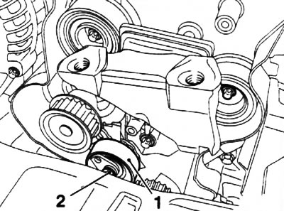
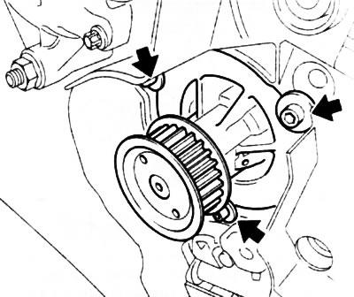
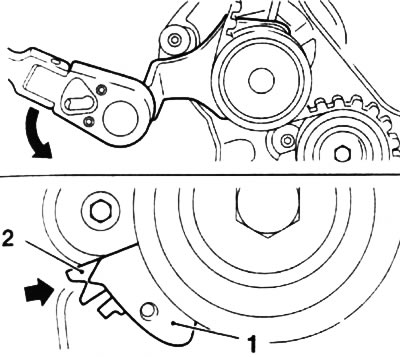
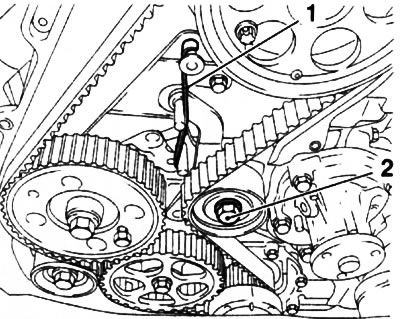
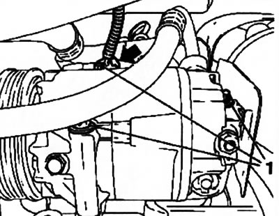
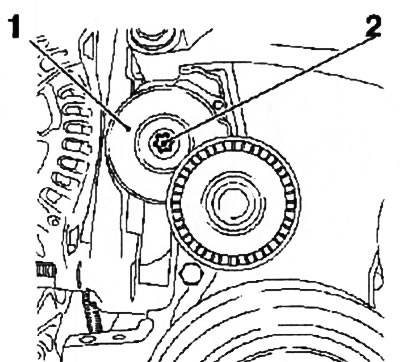
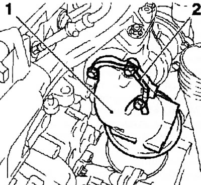
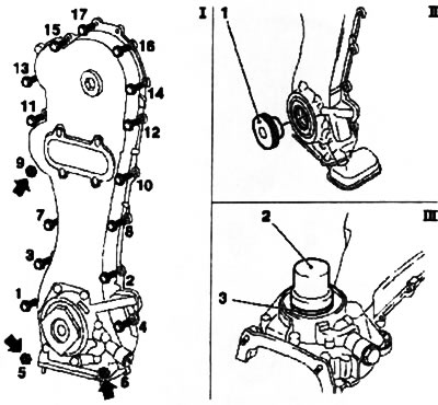
4. Remove the locking pin and loosen the multirib belt tensioner. Remove the fixing bolt (see resist. illustration) and remove the device from the engine.
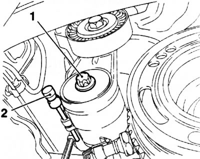
8.4. To remove the tensioner, remove the locking rod (2) and remove the fixing screw (1) (engines Z14XE/Z16XE/Z18XE)
5. Set the piston of the first cylinder to the TDC position of the compression stroke (see Section 6).
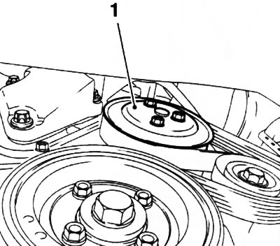
6. Remove the crankshaft pulley (see Section 5), then reinstall the fixing bolt and secure the timing belt drive wheel with it.
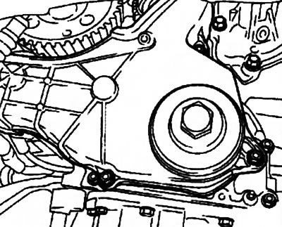
7. Turn out a fixing bolt (see resist. illustration) and remove the lower timing cover.
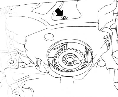
8.7. The arrow indicates the bolt of the lower timing cover (engines Z14XE/Z16XE/Z18XE)
8. Remove the right engine mount (see Section 5).
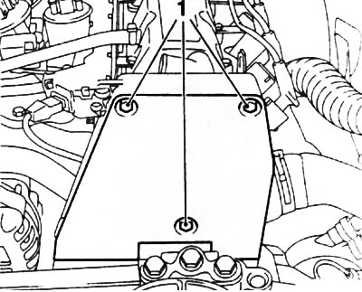
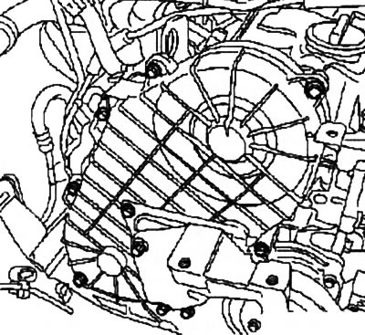
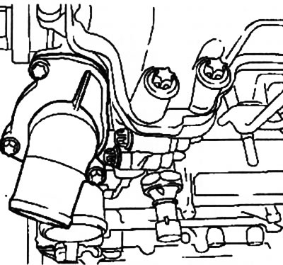
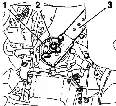
9. Turn out 3 screws of fastening of the top cover of GRM (see resist. illustration) and remove the cover.
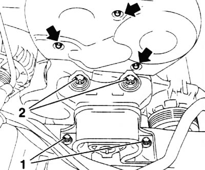
8.9. Mounting bolts: right engine mount - 1 and 2, upper timing cover - indicated by arrows (engines Z14XE/Z16XE/Z18XE)
10. Disconnect the camshaft sensor wiring connector, on the Z16XE engine, remove the 2 bolts and remove the sensor from the cylinder head.
11. Check the position of the TDC for the piston of the first cylinder of the engine, check the coincidence of all marks (see illustration 8.11, I and III) and fix the position of the camshafts with a special tool (see illustration 8.11, II).
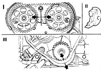
8.11. Checking the TDC position on the example of the Z18XE engine (the arrows indicate the position of the marks with the crankshaft pulley removed): II. Special fixture KM-852
Note: If the marks on the gears do not match, it is not necessary to fix the camshafts.
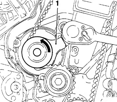
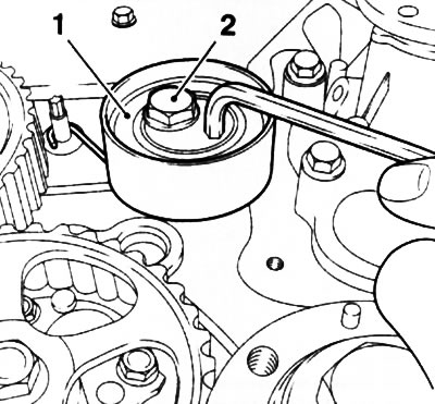
12. Loosen the fixing bolt and turn the toothed belt tension roller by the adjusting eccentric clockwise using a hex bar wrench (see resist. illustration) tighten the bolt until the tension roller pointer is in front of the left stop. If necessary, mark the direction of rotation of the belt and remove it. A belt that has characteristic signs of wear, kinks and damage must be replaced without fail.
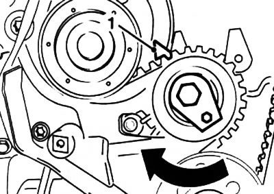
8.12. Pointer (1) toothed belt tensioner (engines Z14XE/Z16XE/Z18XE)
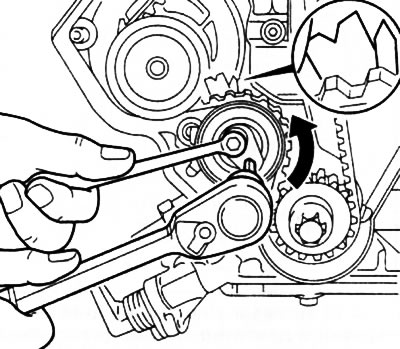
13. If, when checking the adjustment of the valve timing, the marks on the gear wheels of the timing mechanism did not match, it is necessary, after removing the belt, by turning the camshafts, set the marks to the required position and fix them with a special device (see illustration 8.11, II).
Attention: With the belt removed, do not change the position of the crankshaft.
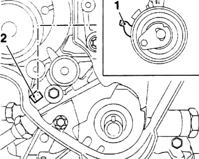
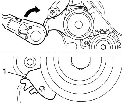
14. If necessary, unscrew the fixing bolt and remove the toothed belt tension roller (see resist. illustration). The guide roller is removed in the same way.
8.14. fixing bolt (2) toothed belt tensioner (engines Z14XE/Z16XE/Z18XE)
Installation
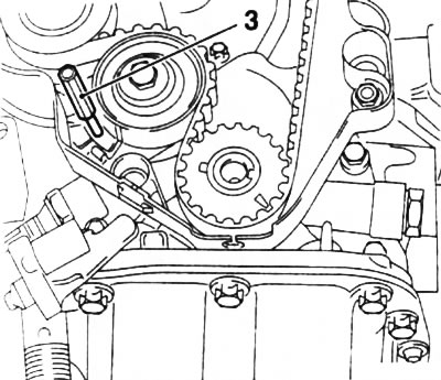
15. Install (if filmed) guide and tension rollers of the toothed belt. The idler pulley stop lever must be installed in the guide on the oil pump housing (see resist. illustration).
8.15. Lock lever (1) guide roller must be installed in the guide (2) on the oil pump housing (engines Z14XE/ Z16XE/Z18XE)
Note: The tensioner fixing bolt is fully tightened to the required torque only after adjustment (see below).
16. Install the belt on the wheels and rollers so that the pulling branch (right - if you look at the engine from the timing drive side) has been tightened, be sure to check the direction of rotation of the belt. Check alignment of all timing marks.
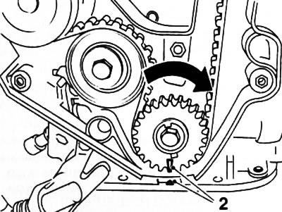
17. After replacing / removing the belt, it is necessary to adjust its tension, for which loosen the fastening bolt (if the video was not filmed) and turn the toothed belt tensioner (see resist. illustration) behind the adjusting eccentric in the direction of the arrow so that the tension roller pointer is in front of the right stop, tighten the bolt.
8.17. Toothed belt tension (engines Z14XE/Z16XE/Z18XE)
Note: On the Z16XE engine, this operation is performed from under the engine. To check the position of the tension roller pointer, you must use a special viewing mirror.
18. Remove the KM-852 tool, smoothly turn the crankshaft 2 full turns clockwise and set the piston of the first cylinder to the TDC position. To control the position, install the KM-852 fixture again, if no adjustment is required, remove it. When labels do not match (see illustration 8.11) remove and reinstall the toothed belt.
19. Slightly loosen the toothed belt tensioning roller bolt, turn the adjusting eccentric clockwise so that the position of the pointer corresponds to that shown on the resist. illustrations. Tighten the idler pulley mounting bolt to the required torque.
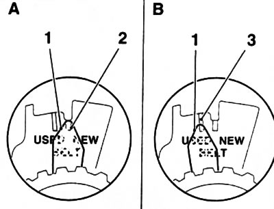
8.19. Toothed belt tension adjustment: 1. Tension roller pointer; 2. Pointer position when installing a new belt (NEW); 3. Pointer position when installing a belt already used (USED)
20. Once again smoothly rotate the crankshaft 2 full turns and set the TDC position. If, after turning the crankshaft, the timing marks do not match, reinstall the belt, if the tension roller pointer deviates from the standard position, repeat the procedure for tensioning the toothed belt.
21. Installation of other removed components is made in an order, the return to an order of removal. On the Z16XE engine, lubricate the camshaft position sensor mounting bolts with a fixing compound.
Z16SE engine
Note: On these models, the procedure for removing the toothed belt is almost the same as on the Z14XE/Z16XE/Z18XE engines. The description below only highlights the differences.
Attention: When the toothed belt is loosened / tensioned on these engines, the water pump housing is displaced, which can lead to a violation of the tightness of its seal. It is recommended that when replacing the toothed belt, also remove the water pump to replace its seal (see chapter 3).
Removing
22. Turn out 3 bolts and remove the top cover of a gear belt (see resist. illustration).
8.22. bolts (1) fastening the upper timing cover (Z16SE engine)
23. Remove the crankshaft pulley (see Section 5), then reinstall the fixing bolt and secure the timing belt drive wheel with it. Loosen the fixing screws (see resist. illustration) and remove the lower timing cover.
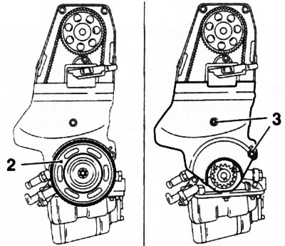
8.23. bolts (3) fastening the lower timing cover (Z16SE engine): 2. Crankshaft pulley
24. Remove the right engine mount (see Section 5).
25. Check the TDC position for the piston of the first cylinder of the engine (see Section 6), - the position of the marks with the crankshaft pulley removed is shown in resist. illustrations.
8.25. Label Alignment (2) in the TDC position for the piston of the first cylinder with the crankshaft pulley removed (Z16SE engine)
26. Drain the coolant (see chapter 3) and remove the 3 water pump mounting bolts (see resist. illustration).
8.26. bolts (indicated by arrows) water pump mounts (Z16SE engine)
27. Against the force of the spring, press the toothed belt tensioner upwards, align the holes and fix the roller in the depressed position with a suitable mandrel (see resist. illustration).
8.27. Fixing the tension roller of the toothed belt in the depressed position with the help of a mandrel (3) (Z16SE engine)
28. Turn the water pump with a wrench or special tool KM-421-A in the direction indicated by the arrow (see resist. illustration) and loosen the toothed belt tension.
8.28. Loosening the tension of the toothed belt using a special tool KM-421-A (1) (Z16SE engine)
29. Remove the toothed belt. If necessary, pre-mark the direction of its rotation.
Attention: With the belt removed, do not change the position of the crankshaft.
Installation
30. Install the water pump (if filmed) with a new O-ring, do not tighten the fixing screws.
31. Install the toothed belt on the wheels so that the pulling branch (right - if you look at the engine from the timing drive side) has been tightened, be sure to check the direction of rotation of the belt. Check the TDC position of the compression stroke for the piston of the first cylinder - all marks must match. Otherwise, tighten the corresponding shaft by the required amount.
32. Slightly wring out the tension roller of the toothed belt, remove the mandrel and release the tension roller.
33. Using the KM-421-A special tool, turn the pump in the direction indicated by the arrow and set the tensioner pointer in front of the upper stop (see resist. illustration). In this position, tighten the water pump mounting bolts.
8.33. Toothed belt tension (Z16SE engine): 1. Pointer
34. Smoothly turn the crankshaft 2 full turns clockwise and set the piston of the first cylinder to the TDC position - the water pump should not move.
35. Loosen the water pump mounting bolts, turn the pump counterclockwise so that the position of the pointer corresponds to that shown on the resist. illustrations. Tighten the water pump mounting bolts to the correct torque.
8.35. Final pointer position (1) toothed belt tension (Z16SE engine): 2. Installation mark
36. Once again smoothly rotate the crankshaft 2 full turns and set the TDC position. If, after cranking the crankshaft, the timing marks did not match, reinstall the belt, if the tension roller pointer deviated from the standard position, repeat the procedure for tensioning the toothed belt.
37. Reinstall all removed components. Fill the system with coolant and adjust if necessary (see chapter 1).
Y17DT engines (L) /Z17DTH)
Note: In general, the procedure for removing/installing the toothed belt on these models is the same as on gasoline engines. The description below only highlights the differences.
Removing
38. Disconnect the wiring from the generator (see chapter 5).
39. Disconnect the cable duct and vacuum lines in front of the top timing belt cover.
40. On the Z17DTH engine, disconnect the wiring connectors of the camshaft sensor and the air pressure sensor. Remove the camshaft sensor.
41. Remove the top timing belt cover (see resist. illustration).
8.41. Top Timing Belt Cover (Z17DTH engine)
Note: Bolts of various lengths are used to fasten the cover, remember or mark the installation position of the bolts.
42. Remove the right engine mount and dismantle the right mount bracket (see Section 5).
43. Loosen the bolts securing the water pump drive pulley (see resist. illustration). Remove the multirib belt, then completely unscrew the bolts and remove the pulley.
8.43. Pulley (1) water pump drive (on the example of the Z17DTH engine)
44. On the Z17DTH engine, disconnect the wiring from the starter (see chapter 5).
45. Remove 4 bolts and remove the crankshaft pulley (see Section 5).
46. Turn out fixing bolts and remove the bottom covers of a gear belt (see resist. illustration).
8.46. Bottom Timing Belt Cover
47. Set the engine to TDC (see Section 6).
48. On Y17DT / Y17DTL engines, fix the tension roller with an M10 bolt by screwing it through the bottom hole of the roller into the cylinder block. Loosen the roller mounting bolt and remove the tension spring (see resist. illustration).
8.48. Bolt (2) fasteners and spring (1) toothed belt tensioner (Y17DT engine)
49. On the Z17DTH engine, loosen the timing belt tensioner bolt (see resist. illustration), turn the tension roller 90°with a socket wrench (1/4 turn) counterclockwise and lock the roller in this position by tightening the fixing bolt.
8.49. fixing bolt (2) tension roller (1) toothed belt (Z17DTH engine)
50. Remove the toothed belt. If necessary, mark the direction of its rotation.
Installation
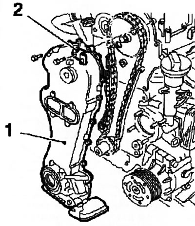
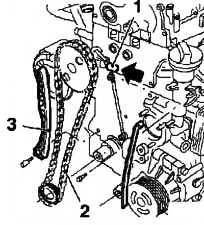
51. Install the toothed belt, observing the direction of rotation, on the drive gears in the following sequence: crankshaft drive gear, oil pump wheel, injection pump wheel and camshaft wheel (see resist. illustration).

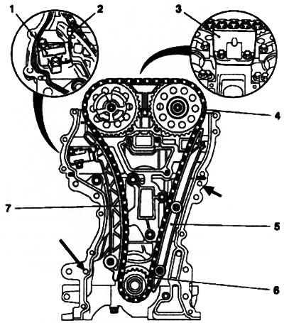
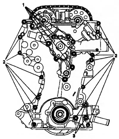
8.51. Timing belt installation (on the example of the Z17DTH engine): 1. Camshaft gear; 2. Injection pump gear; 3. Timing belt tensioner; 4. Oil pump gear; 5. Crankshaft gear; 6. Mark for checking the TDC on the oil pump housing; 7. Mark for checking the TDC on the crankshaft gear
Note: The injection pump and timing drive wheels must be fixed with bolts, the marks on the crankshaft mounting flange and the oil pump housing must match.
52. Install the tension spring, loosen the tension roller mounting bolt and release the roller - the belt will tighten. Turn out fixing bolts from gear wheels of TNVD and a camshaft.
53. Rotate the crankshaft at the center bolt 60°against the direction of engine rotation (counterclock-wise) and tighten the idler pulley mounting bolt to the required torque.
54. Slowly turn the crankshaft 2 full turns clockwise and set the piston of the first cylinder to the TDC position of the compression stroke (see Section 6), - the marks on the crankshaft flange and the oil pump housing must match (see illustration 8.51). Screw the adjusting bolts into the gears of the injection pump and timing drive - if at least one of the bolts is not screwed in (the holes on the wheel and the motor housing did not match), reinstall the toothed belt.
55. Installation of removed and disconnected components is carried out in the reverse order of dismantling. When installing the crankshaft pulley, it is necessary to align the axis of the mounting flange with the hole in the pulley, do not forget to replace the pulley mounting bolts. Tighten all fasteners to the required torque (see specs). The water pump mounting bolts are finally tightened after installing the multirib belt. Upon completion of work, check the coolant level and, if necessary, make appropriate adjustments.
56. Instructions for installing the toothed belt tensioner roller on the Z17DTH engine: install the spring and screw in the roller mounting bolt. Rotate the idler roller about 180°counterclockwise and tighten the fastening (clamping) bolt with a force of approximately 40 Nm.
Z10XE engines (P) /Z12XE/Z14XEP
Note: The following is a description of the timing chain removal/installation procedure for the Z10XEP engine. equipped with an air conditioning system. For other engines, this procedure is almost completely the same, but some additional operations may be required related to the layout of the units.
Removing
57. Disconnect the wire from the negative terminal of the battery (see chapter 5), drain the coolant (see chapter 3) and remove the air cleaner (see chapter 4).
58. Disconnect the heating system hoses and disconnect the electrical wiring connectors shown in Ref. illustrations.
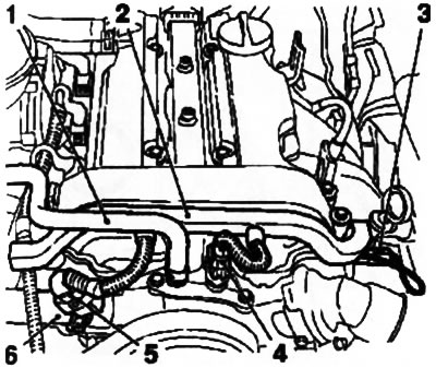
8.58. Heating hoses and engine management wiring connectors (on the example of the Z10XEP engine): 1. Throttle body heating hose; 2. Cable channel box; 3. Wiring connector for oil pressure sensor; 4. Wiring connector for coolant temperature sensor; 5. Connector wiring sensor camshafts; 6. Heating supply hose
59. Disconnect the upper and lower cooling system hoses from the water pump assembly (see chapter 3).
60. Remove the ignition module (see chapter 5), turn out fixing bolts and remove a cover of a head of cylinders.
61. Remove the right front wheel (see chapter «Introduction»), remove the multirib belt cover (see Section 5) and drain the oil from the crankcase (see chapter 1).
62. Remove the exhaust system (see chapter 4).
63. Disconnect the generator wiring (see chapter 5), lock the tension roller and remove the multi-ribbed belt from the crankshaft pulley (see Section 7).
64. Press the tension roller, remove the KM-6130 locking device and release the roller. Turn out the fixing bolts of the tensioner (see resist. illustration).
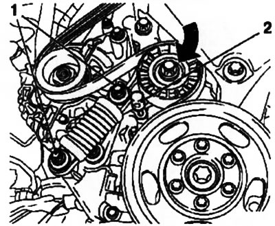
8.64. bolts (1) fastening of the multi-ribbed belt tensioner (on the example of the Z10XEP engine): 2. Fixture KM-6130
Attention: The tensioner must be in a vertical position (the arrow printed on the device is pointing up), otherwise the damping fluid may leak out and the tensioner may fail!
65. Remove the generator (see chapter 5) and remove the engine oil pan (see Section 12).
66. Install a set of special tools for removing the right engine mount (see Section 5) and loosen the mounts.
67. Remove 3 bolts (see resist. illustration), separate the A/C compressor and set it aside or tie it to the load-bearing parts of the body.
8.67. bolts (1) fastenings of the compressor K/V (on the example of the Z10XEP engine - with the corresponding configuration)
Warning: Be careful - the tightness of the air conditioning system must not be broken! For safety precautions when handling refrigerant, see Chapter 3. In case of uncertainty in your abilities, seek help from specialists!
68. Remove the right engine mount (see Section 5) and remove the multirib belt.
69. Turn out 3 fixing bolts and remove a pulley of a drive of the water pump.
Note: The bolts must be loosened before the multirib belt is put on.
70. Turn out a fixing bolt and remove the multirib belt tensioner from the engine.
71. Turn out 3 bolts and remove a connecting branch pipe of system of cooling (see resist. illustration).
8.71. Connecting branch pipe of the cooling system (on the example of the Z10XEP engine)
72. Set the piston of the first cylinder to the TDC position of the compression stroke (see Section 6). Turn out 6 bolts of fastening of a pulley of a cranked shaft, holding a pulley from turning by the central bolt (see Section 5), and remove the pulley.
Note: When removing the pulley, the crankshaft locking tool must be removed.
73. Holding the crankshaft from turning with the help of the KM-956-1 / -2 tool (see resist. illustration), loosen the central bolt of the crankshaft mounting flange - use the help of an assistant.
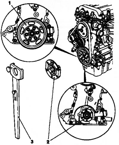
8.73. Pulley (1) and trunnion (2) pulley mounting (on the example of the Z10XEP engine): 3. Device KM-956-1/-2
Note: On other engines, a special tool KM-6013 may be additionally required, which is installed on the flange during this operation. The KM-952 fixture must be removed from the mounting hole.
74. Install the KM-952 tool again, completely unscrew the central bolt and remove the mounting flange.
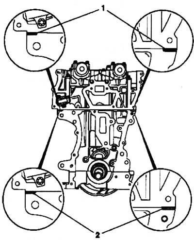
75. Turn out 2 M10 bolts and 14 lower bots MB fastening the timing cover (see resist. illustration). Lower the car, turn out 4 bolts of fastening and remove the water pump. Then remove 4 more upper mounting bolts and remove the timing cover from the engine.
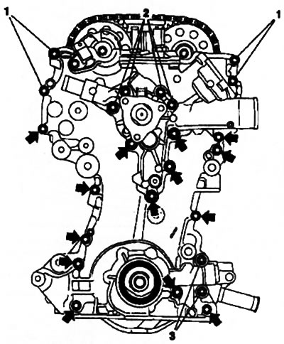
8.75. Timing cover fastening (on the example of the Z10XEP engine) - the arrows indicate the lower mounting bolts M6: 1. Top bolts; 2. Upper water pump mounting bolts; 3. Bottom bolts M10
Note: Bolts of various lengths are used for fastening - remember or mark their installation position.
76. Pull back and fix the chain tensioner using the KM-955-1 tool (see resist. illustration). Remove guides (alternately - (3), (5), (7)) and remove the chain from the crankshaft drive sprocket. Remove the timing cover gasket, clean the mating surfaces.
8.76. Removing the chain (4) timing drive (on the example of the Z10XEP engine) - the arrows indicate the installation locations of the guide bushings: 1. Chain tensioner; 2. Adaptation KM-955-1; 3, 5, 7. Guides; 6. Crankshaft drive gear
77. Using a suitable tool, carefully remove the crankshaft front oil seal from the timing cover seat - do not damage the seating surfaces.
Note: The oil seal must be replaced every time the timing chain is replaced/removed.
Installation
78. Lubricate the outer surfaces of the new oil seal with silicone grease (white) and install the oil seal using the KM-960 tool (see resist. illustration) into the seat of the timing cover.
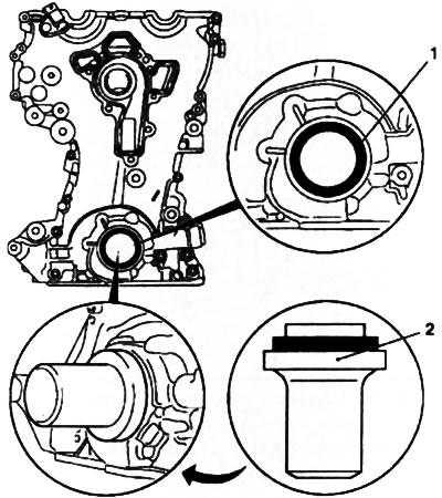
8.78. Installing the front oil seal (1) crankshaft (for example the Z10XEP engine): 2. Adaptation KM-960
79. Remove the remains of the old from the timing cover and install a new water pump gasket on the cleaned surface - make sure that the guide bushings are installed correctly (see resist. illustration) Install the water pump to the drive cover, securing it with 3 short bolts.
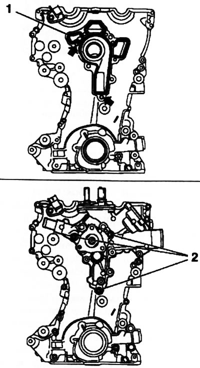
8.79. Water pump installation (Z10XEP engine) - the arrows show the installation locations of the guide bushings: 1. Places for applying the sealant; 2. Installation locations of the water pump short fixing bolts
80. Remove elastomer pads (see resist. illustration) joints of the block head with the cylinder block and replace with new ones, having previously lubricated them with silicone sealant (gray color), by applying a bead of sealant approximately 2 mm thick. In the absence of elastomer gaskets, the joints of the mating surfaces can be filled with sealant without installing gaskets.
8.80. Replacement of elastomer gaskets (1) (Z10XEP engine): 2. Filling joints with silicone sealant
Attention: Installation of the timing cover must be completed within 10 minutes after applying the sealant!
81. Install a new timing cover gasket on the engine - make sure the guide bushings are installed correctly (see illustration 8.76).
82. Install the crankshaft drive sprocket on the shaft and install the timing chain on the camshaft sprockets - pulling (right) the chain branch must be taut. Install the guides in the reverse order of their removal (see paragraph 76).
83. Install the timing cover and tighten alternately, in accordance with that indicated on the resistance. illustrations by numbering, fixing bolts.
8.83. Timing cover installation (Z10XEP engine): 1. Water pump mounting bolts (long); 2. Bolts for fastening the drive cover M6; 3. Bolts for fastening the drive cover M10
84. Remove adjusting devices KM-952 and KM-953 from the engine. With the help of special devices (see above) Install the crankshaft mounting flange.
85. Check and adjust the valve timing (see Section 6) and reinstall the remaining components that were removed in the reverse order of their removal. Pour oil into the lubrication system and coolant into the engine cooling system, check the systems for leaks.
Z13DT engine
Removing
86. Disconnect the wire from the negative terminal of the battery (see chapter 5), remove the multirib belt cover (see Section 5) and drain the coolant (see chapter 3).
87. Remove the air cleaner (see chapter 4) and set the piston of the first cylinder to the TDC position of the compression stroke (see Section 6).
88. Remove the exhaust system (see chapter 4).
89. Loosen 4 crankshaft pulley bolts (see Section 5) and remove the multirib belt (see Section 7). Then completely unscrew the fixing bolts and remove the pulley.
90. Turn out a fixing bolt and remove a tension roller of a multirib belt (see resist. illustration).
8.90. Bolt (2) tension roller attachment (1) (Z13DT engine)
91. Drain the crankcase oil (see chapter 1).
92. Lower the car and remove the turbocharger air outlet (see resist. illustration), and then the heat exchanger tube and the oil supply line - be careful not to burn yourself on the exhaust manifold heat shield.
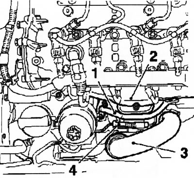
8.92. Connecting lines of various engine systems (Z13DT engine): 1. Water tube heat exchanger; 2. Exhaust manifold heat shield; 3. Turbocharger air pipe; 4. Supply oil line
93. Turn out 4 bolts and remove the oil filter heat exchanger (see resist. illustration).
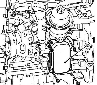
8.93. heat exchanger (1) oil filter (Z13DT engine)
94. Bend the retaining plate tabs. Remove 3 bolts and separate the catalytic converter (see resist. illustration).
8.94. plate (2) catalytic converter mountings (1) (Z13DT engine)
95. Install the KM-662-C tool on the crankshaft flange (see resist. illustration). Holding the crankshaft from turning with the help of the device, loosen the central fixing bolt - use the help of an assistant.
8.95. Install the KM-662-C tool (3) on the flange (1) crankshaft and loosen the central fixing bolt (2) (Z13DT engine)
Attention: The bolt has a left-hand thread!
96. Block the engine flywheel from turning by installing the KM-46785 tool in the hole on the clutch dome - be careful when installing the tool.
97. Remove the engine oil pan (see Section 12). Install the special tool and remove the right engine mount (see Section 5), and then the bracket for mounting the right support.
98. Remove the crankcase ventilation hose (PCV), loosen 4 nuts and remove the water pump of the cooling system (see chapter 3).
99. Turn out a bolt and remove a bracket of fastening of a plait of electroconducting from a timing case cover (see resist. illustration). Turn out 14 bolts, release 3 fixing nuts and remove the timing cover assembly with the oil intake from the engine.
8.99. brace (2) fixing the wiring harness on the cover (1) timing (Z13DT engine)
100. Press the hydraulic timing chain tensioner (see resist. illustration), fix with tool KM-955, unscrew 2 bolts and remove the tensioner. Turn out a bolt and remove a level of a tensioner. Remove the timing chain from the sprockets.
8.100. Chain (2) timing drive (Z13DT engine) - the arrow indicates the direction of pressing the tensioner: 1. Hydraulic tensioner; 3. Tension bar
Installation
101. Installation is carried out in the reverse order of removal. Before installing the timing cover, remove the remnants of the old and apply a layer of fresh sealant (e.g. Loctite 5900) to mating surfaces. When installing, center the cover on the crankshaft using special tool KM-4677 5 (see resist. illustration). Tighten the fasteners in the order shown.
8.101. Installing the timing cover (Z13DT engine) - the arrows indicate the fastening nuts: 1. Fixture EN-46775; 2. Fixture EN-46776; 3. Crankshaft oil seal
102. Before fixing the crankshaft flange, using a suitable tool, carefully remove the front shaft seal from the seat - do not damage the seating surfaces. Lubricate the outer surfaces of the new oil seal with fresh engine oil and install the oil seal using tool EN-46776 (see illustration 8.101) into the seat of the timing cover.
Visitor comments