


Contents: Engines Z10XE(P)/Z12XE/Z14XE (P) ⬇ Engines Z16XE/Z16SE ⬇ Z18XE Engine ⬇ Z13DT Engine ⬇ Y17DT(L) Engines ⬇ Z17DTH Engines ⬇
Engines Z10XE(P)/Z12XE/Z14XE (P)
9. Disconnect both cables from the battery (see Section 8). Raise and support the front of the vehicle on stands.
10. On Corsa-Eco models, remove the crankcase guard (see Chapter 2).
11. On Z10XE(P) engines, remove the generator (see Section 10).
12. Loosen the 2 nuts and disconnect the electrical wiring from the starter (see accompanying illustration).
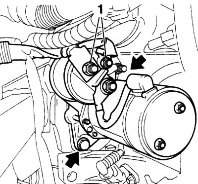
12.12. Bolts (indicated by arrows - the second bolt is not visible in the illustration) starter mounts (Z10XE(P)/Z12XE/Z14XE(P) engines): 1. Electrical wiring fastening nuts
13. Remove 2 bolts (see illustration 12.12), remove the starter and pull it out of the engine compartment downwards.
14. Installation is carried out in the reverse order of removal.
Engines Z16XE/Z16SE
15. Disconnect both cables from the battery (see Section 8). Raise and support the front of the vehicle on stands.
16. Disconnect the lambda probe wiring connector.
17. Remove the bolt and disconnect the central ground cable from the cylinder block.
18. Loosen the 2 nuts and disconnect the electrical wiring from the starter.
19. Unscrew 2 bolts, remove the starter and pull it out of the engine compartment downwards.
20. Installation is carried out in the reverse order of removal.
Z18XE Engine
21. Disconnect both cables from the battery (see Section 8). Raise and support the front of the vehicle on stands.
22. Disconnect the lambda probe wiring connector, unscrew the 2 bolts and remove the exhaust system inlet pipe support bracket (see accompanying illustration).
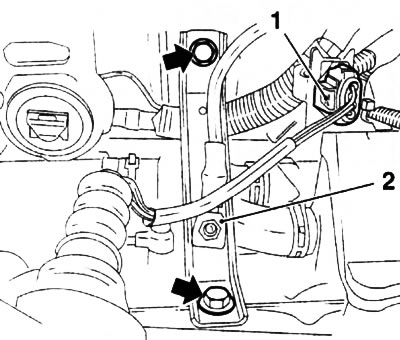
12.22. Bolts (indicated by arrows) support bracket fastenings (engine/Z18XE): 1. Lambda probe wiring connector; 2. "Ground" cable
23. Loosen the 2 mounting nuts (see accompanying illustration) and disconnect the supply wiring from the starter, as well as the ground cable.
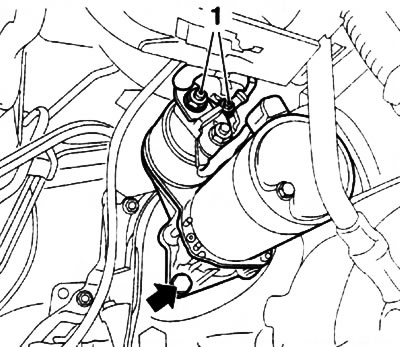
12.23. Nuts (1) for fastening the starter electrical wiring (z18XE engines) - the arrow indicates the lower starter mounting bolt (the second one is not visible in the picture)
Z13DT Engine
26. Disconnect both cables from the battery (see Section 8).
27. Remove the manual transmission gear shift module.
28. Remove the cover on the manual transmission housing and unscrew the upper starter bolt.
29. Raise and support the front of the vehicle on stands.
30. Loosen the 2 nuts and disconnect the electrical wiring from the starter.
31. Unscrew the lower starter bolt, remove the starter and take it out of the engine compartment.
32. Installation is carried out in reverse order.
Y17DT(L) Engines
33. Disconnect both cables from the battery (see Section 8).
34. On Meriva models, remove the battery (see Section 8), disconnect the electrical wiring from the fuel filter, remove the filter from the mounting clamp and move it to the side (see Chapters 1 and 4), unscrew 4 bolts and the battery tray.
35. Remove the upper starter mounting bolt, disconnecting the ground cable.
36. Raise and support the front of the vehicle on stands.
37. Remove the gear shift lever support bracket (see Chapter 6).
38. Disconnect the crankshaft sensor connector.
39. Disconnect the vacuum hose from the solenoid valve (see accompanying illustration).
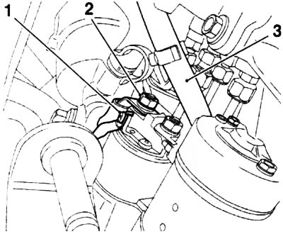
12.39. Bolt (1) and nut (2) for fastening the starter wiring (Y17DT(L) engines): 3. Vacuum hose
40. Place a container underneath to collect the oil, loosen the clamp and disconnect the return oil hose from the cylinder block (see accompanying illustration).
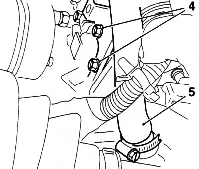
12.40. Bolts (4) for fastening the atmospheric pressure sensor (Y17DT(L) engines)
41. Remove the 2 bolts (and remove the atmospheric pressure sensor holder (see illustration 12.40).
42. Remove the bolt, loosen the nut and disconnect the electrical wiring from the starter (see illustration 12.39).
43. Remove the lower starter mounting bolt and remove the starter from the engine compartment.
45. Installation is carried out in the reverse order. Upon completion of the work, check the engine oil level and make the appropriate adjustments if necessary (see Chapter 1).
Z17DTH Engines
46. Disconnect both cables from the battery (see Section 8).
47. On Meriva models, disconnect the electrical wiring from the fuel filter, remove the filter from the mounting clamp and move it to the side (see Chapters 1 and 4).
48. Remove the upper starter mounting bolt (see accompanying illustration).
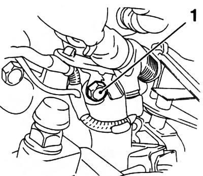
12.48. Upper bolt (1) of starter mounting (z17DTH engine)
49. Raise and support the front of the vehicle on stands.
50. On Meriva models, loosen the 3 nuts and disconnect the exhaust downpipe (see Chapter 4).
51. Separate the wiring harness, unscrew the bolt and loosen the nut securing the starter supply wires, loosen the nut securing the ground cable and disconnect the wiring (see accompanying illustration).
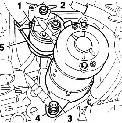
12.51. Fastening the starter wiring (z17DTH engines): 1. Bolt for fastening the supply wire; 2. Nut for fastening the supply wire; 3. "Ground" cable fastening nut; 4. Starter mounting stud; 5. Wiring harness
52. Disconnect the fuel pressure sensor wiring connector.
53. Unscrew the lower mounting pin, remove the starter and pull it out of the engine compartment downwards.
54. Installation is carried out in reverse order.
Visitor comments