
Manual transmission F13, F17 and F17+
1. Loosen the clamp bolt of the gear selector rod (see Section 9).
2. Remove the center console (see chapter 11).
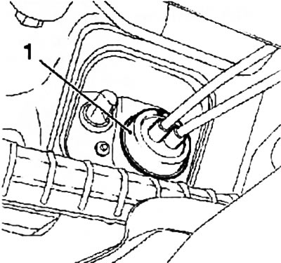
3. Wring out the clamps in the direction indicated by the arrows (see resist. illustration) direction and remove the shift lever.
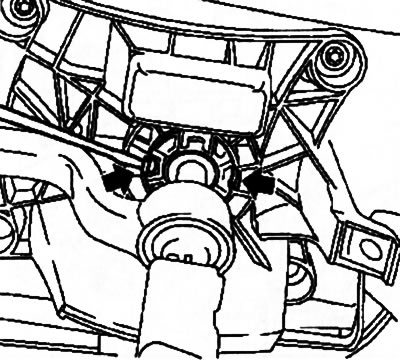
10.3. To remove the gearshift lever, press the latches in the direction indicated by the arrows
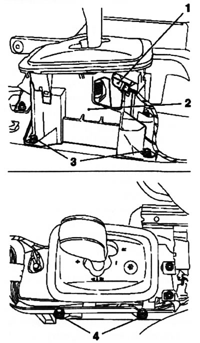
4. Remove the fixing screw, disconnect the wiring (see resist. illustration) and put it aside.
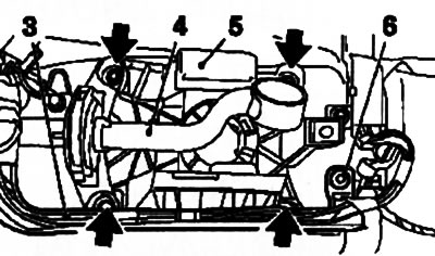
10.4. bolts (indicated by arrows) bracket mounting (5) gear lever (on the example of RKPP 13): 3. Wiring harness; 4. Drive rod; 6. Wiring screw
5. Turn out 4 fixing bolts (see illustration 10.4) and remove the shift lever support bracket along with the drive rod. If necessary, disconnect the rod from the bracket.
6. Installation is carried out in the reverse order. Don't forget to adjust the drive (see Section 9).
Manual transmission F23
7. Remove the center console (see chapter 11).
8. Disconnect the torsos from the gear lever, for which release the tips of the cables from the latches (see Section 9). Then squeeze the coupler locks and release the cables from the holders on the lever support bracket (see resist. illustration).
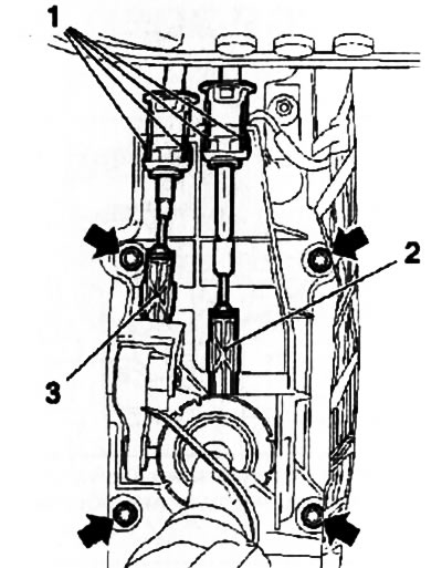
10.8. Release the tips (2 and 3) out of the latches, squeeze the latches (1) couplings and release the cables from the holders (Manual transmission F23) - the arrows indicate the mounting bolts of the bracket
9. Turn out 4 fixing bolts (see illustration 10.8) and remove the shift lever assembly.
10. If necessary, remove the drive cables, for which, using a suitable tool (for example, KM-6042) disconnect the cable ends from the actuating lever on the gearbox and release the cable clamps from the holders (see illustration 10.10a), pulling them back slightly. Disconnect the cable guide sleeve from the bulkhead of the engine compartment (see illustration 10.10b), remember or mark the installation position of the sleeve. Remove the cables through the engine compartment.
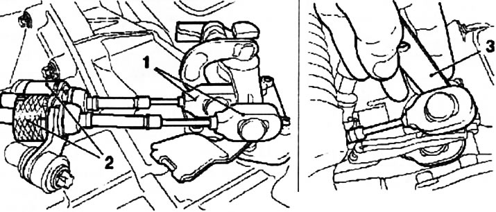
10.10a. Using the KM-6042 tool (3) disconnect the tips (1) drive cables from the actuating lever on the gearbox (Manual transmission F23)
10.10b. Guide sleeve (1) drive cables on the bulkhead of the engine compartment (Manual transmission F23)
11. Installation is carried out in the reverse order. Don't forget to adjust the drive (see Section 9).
Robotic gearbox Easytronic
12. Remove the center console (see chapter 11).
13. Disconnect the connector of the electrical wiring of the gear lever, remove the fixing bolts (see resist. illustration) and remove the lever assembly.
10.13. bolts (3 and 4) mount assembly (2) gear lever (Easytronic)
14. Installation is carried out in the reverse order.
Visitor comments