


Contents: Checking the timing belt tension ⬇ Replacing the timing belt ⬇ Camshaft seals ⬇ Camshaft, camshaft bearing housing…⬇ Hydraulic tappets ⬇ Removal and installation camshaft…⬇ Camshaft oil seal ⬇ Replacing the timing belt ⬇ Removal and installation camshafts ⬇ Replacing the timing belt tension…⬇ Replacing the guide roller ⬇ Removal and installation the…⬇ Replacing the drive chain and…⬇ Distributor shaft drive gear ⬇ Removal and installation the camshaft ⬇ Replacing camshaft bearings ⬇
In 2.0L OHC and DOHC engines, the camshaft is overhead and driven by a toothed belt. However, the timing belt for different engines has a different routing pattern.
The 2.4L engine has a chain drive for the camshaft.
Checking the timing belt tension
ONS engine produced until mid-1995
Checking and tensioning the timing belt should be done on a cold engine. This operation is carried out differently for an engine with a timing belt tension roller and without a tension roller.
Engine with timing belt tension roller
1. Remove the viscous coupling with the fan and brackets as described in the relevant subsection.
2. Remove the alternator and power steering pump drive belt.
3. Remove the shield under the car.
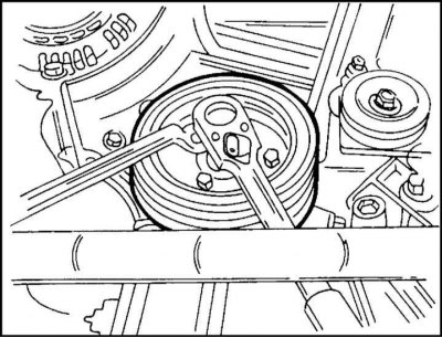
4. Remove the four crankshaft pulley mounting bolts. The pulley is held from turning with a socket wrench as shown in the illustration.
5. Remove the front timing belt cover.
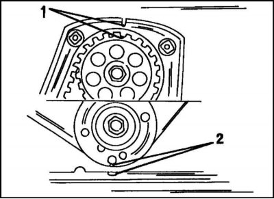
6. Turn the crankshaft in the direction of rotation with a socket wrench so that the marks (2) coincide (illustration). At the same time, the marks (1) on the camshaft gear and the bar behind the toothed belt must coincide.
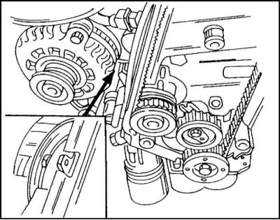
7. Check the coolant pump drive pulley. The lug on the pump must match the corresponding protrusion on the cylinder block, as shown in the illustration.
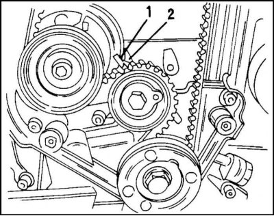
8. Check the timing belt tension. The belt is tensioned properly if the pointer (2) is 4 mm to the left of the mark (2) in the illustration. This check applies to a used belt. A different standard applies to a new belt (see below section Replacing the timing belt).
9. If the timing belt tension is not as specified above, it is necessary to perform adjustment as described in the section "Replacing the timing belt".
Now the engine can be assembled. Tighten the pulley mounting bolts to 20 Nm. Installation of the viscous coupling, V-belt, etc. is described in the relevant sections.
Engine without timing belt tensioner roller
To check the tension of the toothed belt in these engines, there is a special tool from Opel (No. KM-510-A). If it is not available, then the check is performed by the car owner himself based on his own experience. However, such tension requires subsequent checking in a car repair shop.
Checking the belt tension is described below in the section Replacing the toothed belt for engines without a tension roller.
Replacing the timing belt
Engine with tension roller
1. Disconnect the ground cable from the battery.
2. Mark the belt with paint to indicate the direction of rotation and remove the belt as described in Chapter Cooling and heating systems.
3. Place the front of the car on stands.
4. Remove the shield under the car.
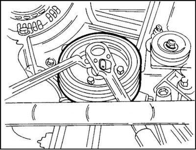
5. While holding the crankshaft from turning as shown in the illustration, loosen the vibration damper mounting bolts. Remove the damper.
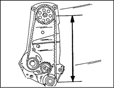
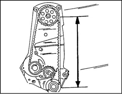
6. Disconnect the cable mount from the timing belt cover and remove the cover. The timing belt routing diagram is shown in the illustration. Install the belt so that its tensioned section is located between the lines indicated by arrows on the drawing.
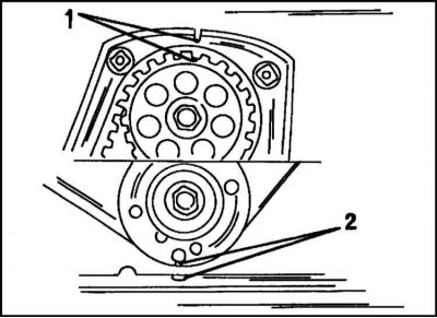
7. Turn the crankshaft in the direction of rotation with a socket wrench so that the marks (2) coincide (illustration). At the same time, the marks (1) on the camshaft gear and the bar behind the toothed belt must coincide.
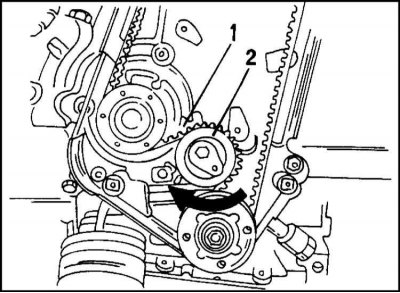
8. Loosen the tension roller mounting bolt and turn the adjusting eccentric to the right in the direction of the arrow, as shown in the illustration, so that the pointer (1) is opposite the left stop.
The belt is now loose and can be removed.
Note: If the belt is to be used again, it must be prevented from coming into contact with oil, grease or from being bent. The best way to store the belt is to hang it on a nail on the wall.
9. Check that the camshaft and crankshaft are in the position shown in the illustration. Otherwise, turn the shaft very slowly. The pistons may hit the valves. Once you feel this, turn the second shaft back.
The coolant pump drive pulley should also be checked as it may not be turning correctly. The lug on the pump body must match the corresponding protrusion on the cylinder block.
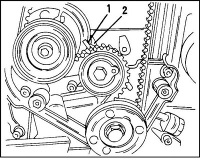
10. Put on the timing belt as shown in the illustration. point 1 on gear wheels. Branch 1 of the belt must be tensioned. Now you need to tighten the belt. The belt is correctly tensioned if the pointer (1) coincides with the mark (2), as shown in the illustration. Below we consider cases where there is no such match.
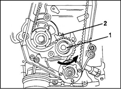
11. Loosen the bolt at the tension roller center and turn the adjusting eccentric (1) in fig. to the left so that the pointer (2) is adjacent to the right stop. Tighten the roller mounting bolt again (25 Nm).
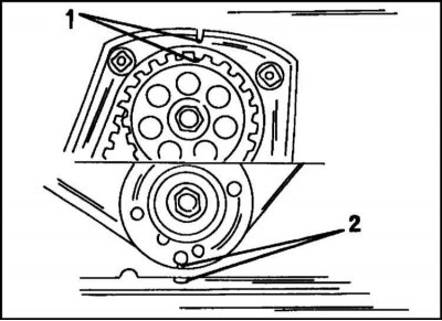
12. Turn the crankshaft exactly two revolutions (using a socket wrench on the pulley mounting bolt) and check if the marks shown in the illustration match.
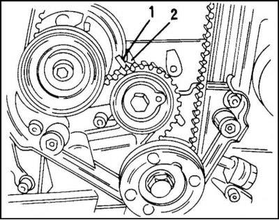
13. Slightly loosen the tension roller mounting bolt and turn the adjusting eccentric to the right (clockwise) so that the pointer (1) and the mark (2) lie opposite each other, as shown in the illustration. Tighten the bolt again to a torque of 25 Nm.
14. Rotate the crankshaft again two full revolutions and check the position of the marks and the eccentric pointer.
Perform other work in reverse order. Tighten the torsional vibration damper with a torque of 20 Nm. Put on the V-belt taking into account its direction of rotation and tension it as described in Chapter Cooling and heating systems.
Reinstall all removed parts.
Engine without timing belt tensioner roller
1. Disconnect the ground cable from the battery.
2. Remove the viscous coupling with the fan and fan shroud (see relevant instructions).
3. Remove the Torx bolts securing the fan pulley. Remove the fan.
4. Remove the top portion of the front timing belt cover.
5. Turn the crankshaft so that the piston of the first cylinder is at TDC.
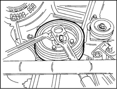
6. Loosen the pulley mounting bolt as shown in the illustration.
7. Remove the lower part of the timing belt cover.
8. Loosen the three coolant pump mounting bolts and push the pump to the side so that the timing belt is loosened and can be removed.
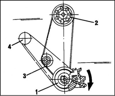
4 – Generator
9. Install the new timing belt as shown in the illustration. First place the belt on the crankshaft sprocket (1), then on the camshaft sprockets (2) and the coolant pump sprockets (3).
10. Now install the crankshaft pulley.
Adjust the timing belt tension. To check the tension of the toothed belt in these engines, there is a special tool from Opel (No. KM-510-A). If it is not available, then the check is performed by the car owner himself based on his own experience. However, this requires later verification in a car repair shop.
Checking the belt tension is described below in the section "Replacing the toothed belt" for engines without a tension roller.
Note: The tension of a used belt is checked on a warm engine. The tension of the new belt is checked on a cold engine.
The following describes how to check the belt tension on an installed engine.
1. Slide the coolant pump outward, allowing some slack in the drive belt, and tighten the pump mounting bolts by hand.
2. Place a socket head on the crankshaft pulley mounting bolt and rotate the shaft from its current position at least a quarter turn to the right.
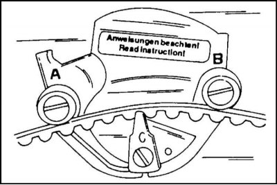
3a. The belt tension control device shown in the illustration.
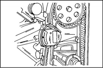
3b. Install the device as shown in the illustration. (between the wheels of the coolant pump and the camshaft).
4. Slowly release the lever of the device, tap the device two or three times and take a reading.
Below are the instrument readings for cold and warm engines. They should not be confused.
5. If the gauge reading does not match the above, loosen the coolant pump mounting bolts and turn the pump. Turning outward increases belt tension, turning inward decreases tension. Tighten the pump mounting bolts again by hand (the pump can't be moved anymore).
6. Remove the instrument and turn the crankshaft two full turns to the right. Check the belt tension again using the method described above. If it matches the above values, tighten the pump mounting bolts. Replace the timing belt covers. Secure the cable harness to the cover.
7. If the above-mentioned belt tension control device is not available, the tension is checked manually on the belt branch between the coolant pump wheels and the camshaft. To do this, try to turn the belt tape with your thumb and forefinger. If the belt can be turned 90°, the tension is adjusted correctly. It is better to overtighten the belt than undertighten it. A loose belt can skip over the teeth of the wheel. The tension adjustment must also be performed on the coolant pump. Additional checks would not be superfluous. A control check must be performed at a car repair shop. Belt skipping can cause serious engine damage and, at a minimum, costly repairs.
OHC 2.0L engine since mid-1995
The camshaft drive matches that of the latest model engines. The control of the toothed belt tension corresponds to the control described above. A toothed belt with a tension roller is installed here, i.e. it is necessary to follow the instructions given in the subsection Engine with a toothed belt tension roller in the Section Checking the toothed belt tension and the instructions for replacing the toothed belt in the subsection Engine with a toothed belt tension roller in the Section Replacing the belt. The belt routing is shown in the illustration. to point 9.
Camshaft seals
Removal and installation of the oil seal in the camshaft housing on the timing drive side and on the gearbox side are different. Both seals can be replaced without removing the engine.
Replacing the seal on the camshaft drive side
1. Disconnect the wiring harness and both hoses from the camshaft bearing housing cover. Now you can remove the timing belt as described above. Be aware of the differences in camshaft drive design.
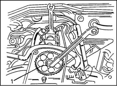
2. Place the wrench on the hexagon of the camshaft (located at the end of the shaft, see illustration.) and use a spanner to unscrew the camshaft wheel mounting bolt. Remove the wheel from the camshaft.
3. Screw a screw into the seal and pull it out of the cylinder head with pliers.
4. Generously lubricate the outer and working surfaces of the new seal with grease and press it in using a pipe, washer and pulley mounting bolt until it stops, as described above.
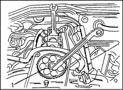
5. Install the wheel on the camshaft and screw in the mounting bolt. While holding the shaft from turning, tighten the bolt (1) in the illustration. torque of 45 Nm.
6. Reinstall the removed parts, including the timing belt. Tighten the camshaft bearing housing cover mounting bolts to a torque of 8 Nm.
Replacing the oil seal on the camshaft side
1. Remove the timing belt (see corresponding description).
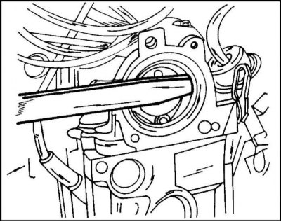
2. Press the seal out of the camshaft bearing housing using a crowbar, as shown in the illustration. Be careful not to damage the case.
3. Lubricate the new seal with grease and press it in place. For pressing, you can use a plate fixed to the threaded holes.
Camshaft, camshaft bearing housing and components
The OHC engine camshaft is located in a separate housing. The engine in question has hydraulic valve lifters that maintain constant valve clearances. The camshaft, bearing housing, hydraulic tappets, rocker arms and seals can be removed independently of each other.
The camshaft bearing housing is removed as follows:
1. Remove the cylinder head (Section Cylinder head and valves).
2. Loosen the bolts and remove the camshaft mounting plate cover.
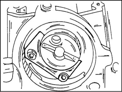
3. Remove the two bolts and remove the camshaft mounting plate (illustration). The camshaft can now be removed from the cylinder head. On the drive side of the shaft using a screw-in self-tapping screw, on the gearbox side in accordance with fig.
If a new camshaft is being installed, all rocker arms must be replaced.
If a used camshaft is to be installed, it is necessary to check the degree of wear of its journals and cams. Measure the inner diameter of the bearings and the outer diameter of the crankshaft journals with a micrometer. Determine the gaps in the mating. If they go beyond the established limits, the camshaft and/or camshaft bearing housing are replaced.
Place the camshaft with its outer journals in prisms or clamp them in the centers of a lathe, and move the measuring tip of the indicator to the central journal. Slowly turn the camshaft and read the indicator reading. If it is more than 0.04 mm, the camshaft must be replaced.
Install the camshaft into place using the pressure plate. Attach the indicator to the end of the shaft and press its measuring tip against the end of the shaft. Move the camshaft forward and backward until it stops and measure the axial clearance. It should be 0.09–0.21 mm. If the gap is outside the established limits, it is necessary to replace the pressure plate or, in extreme cases, the shaft itself.
Check the non-flatness of the upper and lower surfaces of the camshaft bearing housing. In addition, the height of the body must have a certain value, allowing for grinding of the surfaces in case of their deformation.
4. Insert the camshaft into the bearings, lubricating the journals with graphite grease. Be careful not to damage the bearings.
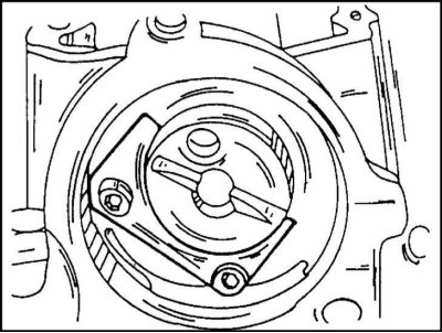
5. Insert the pressure plate into the grooves and tighten the mounting bolts to 8 Nm (see illustration.).
6. Lubricate the seals with oil and carefully press them in using a pipe from both sides of the housing.
7. Install the cylinder head as described in the appropriate section for the OHC engine, taking into account design differences depending on the year of manufacture.
Hydraulic tappets
After removing the camshaft, the hydraulic tappets and rocker arms can be removed or replaced. The specified parts can be replaced without removing the camshaft. However, this requires a special tool to compress the valve spring, which will allow you to remove the pressure element and then remove the pusher.
DOHC Engine
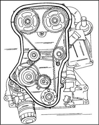
The engine has an automatic tensioner and timing belt guides. The C 20 NE engine has a similar device. The toothed belt guides are made in the form of rollers. The belt routing diagram is shown in the illustration.
Removal and installation camshaft gears
1. Disconnect the ground cable from the battery.
2. Remove the timing belt as described below.
3. Loosen the ignition cable cover mounting bolts and disconnect the plug connection using the tool included in the kit.
4. Disconnect the 2 hoses from the cylinder head cover and unplug the camshaft position sensor plug connection.
5. Remove the cylinder head cover. Please note the presence of sealing rings.
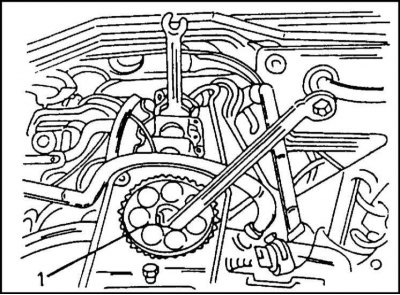
6. Hold the camshaft by the hexagon with a wrench to prevent it from turning, as shown in the illustration. for DOHC engine, remove the gear mounting bolt. On this engine the hex is located directly behind the camshaft wheel.
7. Remove the axle wheels.
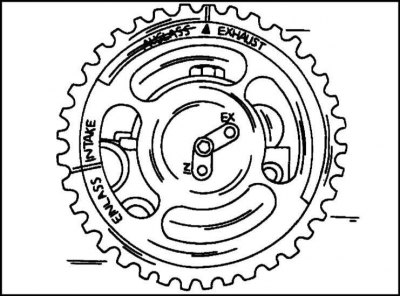
The installation of gear wheels is carried out in accordance with the illustration. The wheel has one hole marked "IN" and a second hole marked "EN". When installing the wheels, keep the following in mind:
1. The intake camshaft pin must fit into the "IN" hole in the wheel.
2. The exhaust camshaft pin must fit into the "EX" hole in the wheel.
3. Screw in the wheel mounting bolt. While holding the camshaft from turning, tighten the bolt to a torque of 50 Nm. From this position, turn the bolt further by an angle of 60±15°.
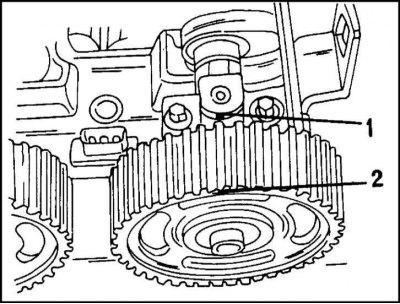
4. Turn the camshaft so that both marks shown in the illustration are aligned. Align the mark (2) on each wheel with the protrusion (1) on the front bearing cover.
5. Install the cylinder head cover with sealing rings. Tighten the mounting bolts to 8 Nm.
6. Install the timing belt as described below.
7. Perform other work in the reverse order of removal. In particular, connect the crankcase exhaust hose, connect the spark plug connectors, camshaft position sensor, and install the ignition cable cover.
Camshaft oil seal
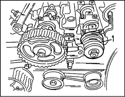
1. The camshaft seal can be replaced after removing the wheel, similar to the procedure described above. The new seal is installed using a pipe, wheel mounting washer (1), as shown in the illustration.
Replacing the timing belt
The timing belt routing diagram is shown in the illustration. above. To remove it, you need to free the end part of the engine.
1. Disconnect the ground cable from the battery.
2. Mark the belt with paint to indicate the direction of rotation and remove the belt as described in Chapter Cooling and heating systems.
3. Place the front of the car on stands.
4. Remove the shield under the car.
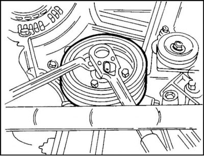
5. While holding the crankshaft pulley mounting bolt as shown in the illustration, loosen the vibration damper mounting bolts. Remove the damper.
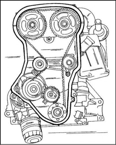
6. Remove the cable guide from the timing belt cover at the front of the engine. The belt routing diagram corresponds to the illustration.
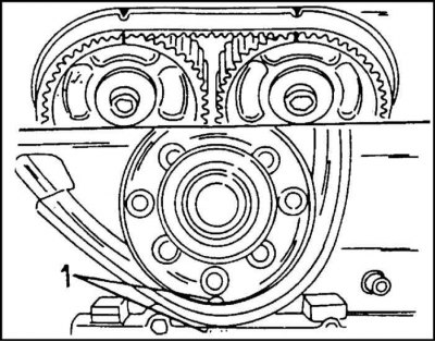
7. The tensioning device of the engine in question is similar to the tensioning device of the OHC engine. First, set the crankshaft to the TDC position. Using a socket head, turn the crankshaft in the direction of rotation so that the mark (1) coincides with the corresponding mark in the lower position (illustration). At the same time, the marks on the camshaft wheels and on the bar behind the toothed belt must coincide, as described above.
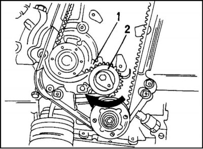
8. Loosen the tension roller mounting bolt and turn the adjusting eccentric to the right in the direction of the arrow, as shown in the illustration, so that the pointer (1) is opposite the left stop.
The belt is now loose and can be removed.
Note: If the belt is to be used, it must be ensured that it does not come into contact with oil or grease and that it is not bent. The best way to store the belt is to hang it on a nail on the wall.
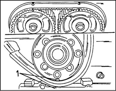
9. Check that the camshaft and crankshaft are in the position shown in the illustration. Otherwise, turn the shaft very slowly. The pistons may hit the valves. Once you feel this, turn the second shaft back. The coolant pump drive wheel should also be checked as it may not be turning correctly. The lug on the pump body must match the corresponding protrusion on the cylinder block.
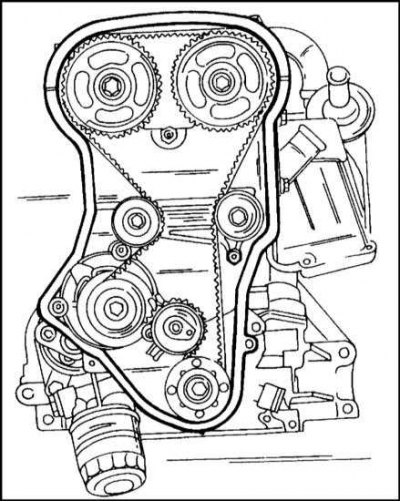
10. Put on the timing belt as shown in the illustration. on gear wheels. The right side of the belt must be taut.
Now you need to tighten the belt. This work can also be performed on an installed engine. This is done according to the service plan after a certain mileage. To do this, it is necessary to provide access to the side of the engine timing drive where the adjusting eccentric is located.
The tension of the toothed belt is carried out in the same way as the tension of the OCH 2.0L engine belt with a tension roller.
11. Other work is performed in the reverse order of removal. The torsional vibration damper is secured with a torque of 20 Nm. Install the V-belt taking into account the direction of its rotation and tension it as described in Chapter Cooling and heating systems for this type of engine.
12. Install all removed parts.
Removal and installation camshafts
With the exception of some differences, removal and installation of the intake and exhaust camshafts is performed in the same way.
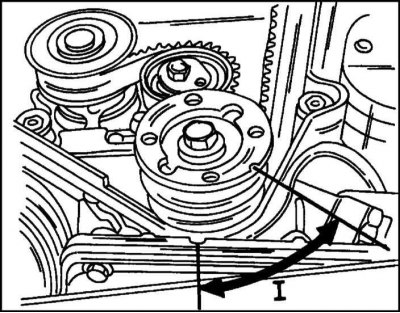
1. Remove the timing belt (see subsection "Removing the timing belt"). Before removing the camshafts, the crankshaft must be set to the position shown in the illustration, where the angle between the lines is 60.
2. Remove the camshaft gears (see subsection "Removing and installing camshafts").
3. Check that the camshaft cap markings are clearly visible. Otherwise, mark the lids.
4. Loosen the cover mounting bolts crosswise in a few turns (1–1.5 turns) so that the covers are free. Remove the covers in order and store them in the order they were installed. The front bearing is a guide bearing.
5. Using a rubber suction cup, remove the hydraulic lifters.
6. Check the camshafts as described for the OHC engine.
The installation of camshafts is performed as follows:
1. Lubricate the camshaft journals and sliding surfaces of the hydraulic tappets with graphite grease. Install the shaft into the bearings.
2. Apply sealant to the front bearing contact surface and install all bearing caps. Check immediately that the markings on the lids match.
3. Tighten the bearing cap mounting bolts crosswise to 8 Nm.
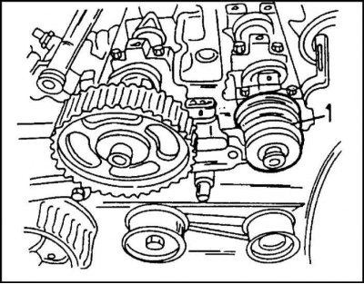
4. Install the new seal as described above (illustration).
5. Install the camshaft timing gears.
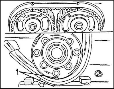
6. Using a socket head, turn the crankshaft in the direction of rotation so that the marks (1) align, as shown in the illustration.
7. Install the timing belt as already described for this engine.
Replacing the timing belt tension roller
The tension roller is removed (the mounting bolts are unscrewed) after removing the timing belt.
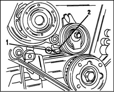
1. When installing the tension roller, pay attention to the illustration shown. locking lever (1). The lever must enter the pump guides (2). The tightening torque of the fastening bolt is 25 Nm. Finally, put on the toothed belt as described above.
Replacing the guide roller
1. One of the rollers is mounted on the holder, the other on the cylinder head. To remove the roller, you need to remove the toothed belt. The roller mounting bolts are tightened to a torque of 25 Nm.
Engine 2.4 l (camshaft chain drive)
Removal and installation the camshaft drive housing
These works were described above when describing the removal of the crankshaft.
Replacing the drive chain and sprockets
A description of this work is given above when describing the removal and installation of the crankshaft of this engine.
Distributor shaft drive gear
The gear is located at the end of the crankshaft. Its removal and installation are described in the description of work related to the camshaft drive. The work is performed without removing the drive housing.
1. Remove the fan with viscous coupling (separate description).
2. Remove the V-belt (separate description).
3. Remove the belt pulley.
4. Remove the seal from the hole in the drive housing as described in the relevant section.
5. Remove the distributor cap.
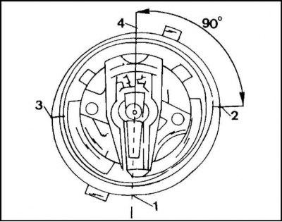
6. Turn the engine so that the piston of the first cylinder is at TDC of the ignition moment. This can be determined by the slider. The runner should point to the groove in the edge of the distributor housing as shown in the illustration.
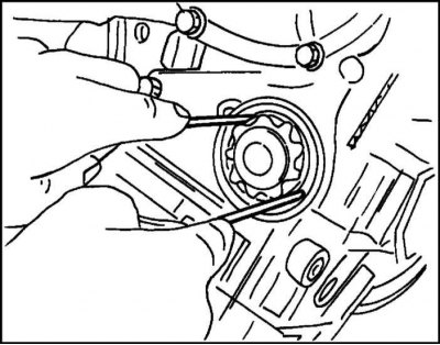
7. Remove the gear. Turn the distributor runner in the opposite direction of rotation. In this case, the gear can be removed. Sometimes it can get stuck. You can remove it with two hooks bent from a wire with a diameter of 3 mm. The ends of the wire are bent at a right angle at a distance of 5 mm. Grab the gear with hooks as shown in the illustration.
The gear installation is performed as follows:
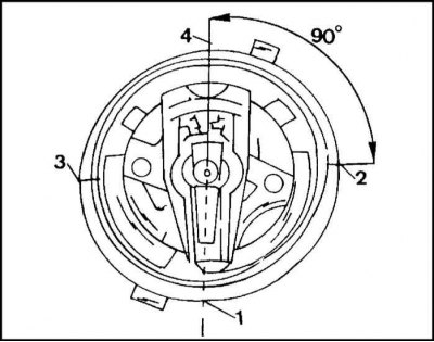
1. Install the gear on the crankshaft with the flange towards the shaft so that the runner occupies the position shown in the illustration.
2. Install the oil seal into the camshaft drive housing as described above.
3. Install the pulley on the crankshaft and put on the V-belt. Tighten the belt (separate description).
4. Install the viscous coupling. Check the position of the runner first.
Removal and installation the camshaft
1. Remove the cylinder head as directed.
2. Remove the camshaft rocker arms and take out the hydraulic tappets.
3. Loosen the bolts and remove the mounting cover from the rear and side of the cylinder head.
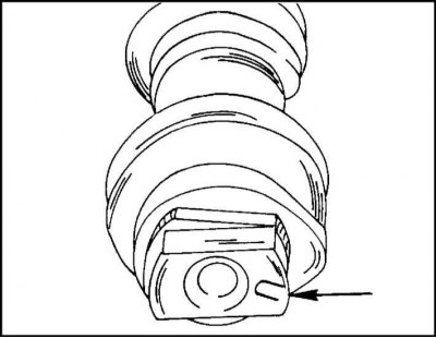
4. Remove the camshaft from the bearings, being careful not to damage the bearing journals and cams.
Note: When replacing the camshaft, pay attention to the markings on the end of the shaft. The illustration shows the location of the "U" marking. In addition, the shaft is color-coded. The nominal size shaft is marked blue/brown. Ground shaft (neck diameter is 0.1 mm smaller) has a purple marking.
The installation of the camshaft is performed as follows:
1. Lubricate the journals and working surfaces of the cams and the upper side of the hydraulic tappets with graphite grease.
2. Insert the camshaft from the front into the cylinder head. Turn the shaft several times and install the covers.
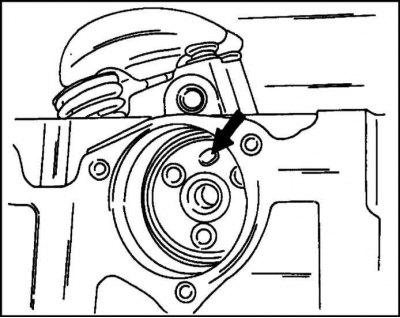
3. Turn the camshaft so that the guide pin is in the position shown in the illustration.
4. Install the hydraulic lifters in place. Put the used pushers back in their places.
5. Install the rocker arms.
6. Install the cylinder head according to the instructions for this engine.
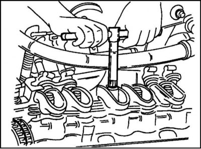
7. Adjust the hydraulic lifters if they were removed. Adjustment requires care.
- Set the piston of the adjustable cylinder to TDC.
- Loosen the adjusting nut as shown in the illustration so that there is no clearance in the valve.
- Tighten the adjusting nut until there is no gap between the valve, rocker arm and tappet.
- From this position, tighten the adjusting nut one full turn.
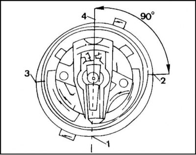
Adjustment occurs in the order of ignition. By removing the distributor cap, you can determine which piston is at TDC by the position of the runner (illustrated). The adjustment sequence can be any. It is only necessary that the adjustment be carried out on a specific cylinder corresponding to the piston position and stroke.
Note: The hydraulic tappets can be adjusted with the engine running.
This is done as follows:
8. Warm up the engine to operating temperature.
9. Remove the cylinder head cover and splash shield.
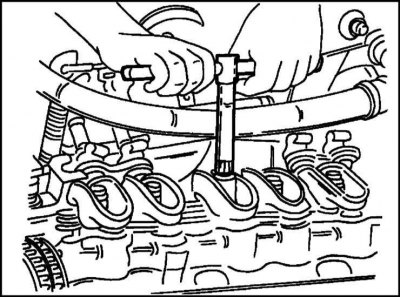
10. Install the socket head, as shown in the illustration, on the rocker arm of the first cylinder and loosen the adjusting nut until the rocker arm begins to click.
11. Tighten the adjusting nut again until the noise stops.
12. Tighten the adjusting screw another quarter turn and wait about 10 seconds until the engine starts to run normally. Turn the adjusting screw another 3 turns.
Replacing camshaft bearings
The camshaft bearing bushings located in the cylinder head can be replaced. If the bushings are worn out, they are pressed out and replaced.
This operation is best performed in a car repair shop, as it requires the use of special equipment.
Visitor comments