
2. On models equipped with F17/F17+, F35 and F40 manual transmissions, press the lock (see resist. illustration) and remove the air supply hose for blowing the rear passenger seats. Disconnect the electrical wiring from the diagnostic connector, remove the 2 bolts and remove the connector mounting bracket.
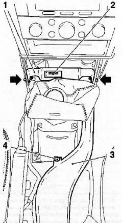
9.2 Bolts (indicated by arrows) bracket mounting (1) diagnostic connector (2): 3. Air supply sleeve; 4. Retainer
3. Disconnect the torsos from the assembly of the gear lever, for which first release the tips of the cables from the latches (see Section 8), and then squeeze the cable holder tabs on the arm assembly and detach them along with the cables.
4. Turn out 4 fixing bolts (see resist. illustration) and remove the shift lever assembly.
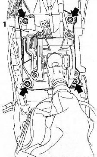
9.4 Bolts (indicated by arrows) mount assembly (1) gear lever (on the example of RKPP 35)
5. If necessary, remove the drive cables, to do this, disconnect the cable guide sleeve from the rear bulkhead of the engine compartment, disconnect the cable ends from the gearshift actuator rod and remove the cable from the holder by slightly pulling back the retaining rings.
6. Installation is carried out in the reverse order. Don't forget to adjust the drive (see Section 8).
Visitor comments