
Note: Depending on the configuration and type of AT, the operations for removing/installing the transmission may differ slightly from those described below.
1. The gearbox can be removed in two ways: together with the engine on the subframe (see chapter 2) or separately from the engine. In the second case, special lifting devices are required - a hoist, a winch or a special transverse beam / rod, which is installed on top of the side members, and a set of rigging equipment. Opel service stations use a cross bar and a special universal kit to hold the engine in a suspended position (see chapter 10).
2. Remove the battery from the tray (see chapter 5). Some models may require removal of the engine cover (see chapter 2) and expansion tank.
3. Disconnect the shift drive cable (see Section 3).
4. Disconnect and lay aside all electrical and other lines routed from above the AT.
On models equipped with AT AF23, disconnect the intake duct (see chapter 4).
5. Turn out the top bolts of fastening of transmission to the block of the engine on VT20-E one, on AF23 two and on AF33 three bolts.
6. Hang the power package using lifting equipment (see chapter 10).
7. Fix the radiator and remove the front bumper cover (see chapter 11).
8. Remove the exhaust system (see chapter 4).
9. Install the right engine mount remover (see Chapter 2, Section 5) and remove the front suspension subframe (see chapter 10).
Note: The tool must remain on the subframe - in this case it is designed to center the AT when it is later installed.
10. Turn out fixing bolts and separate a forward support and an arm of a back support of a suspension bracket of the power unit from a coupling dome (see chapter 2).
11. Drain the ATF, then screw the drain plug into place and tighten to the required torque (see Section 4).
12. Remove the drive shafts, including the intermediate (with appropriate equipment) (see chapter 8).
13. Turn out fixing bolts and remove the left support of the power unit (see chapter 2).
Note: Some models may require the removal of the support mounting bracket as well.
14. Gradually releasing the hoist, lower the power unit by approximately 5 cm - make sure that the communication lines laid from below are not pinched (hoses and wiring) and make sure that nothing prevents the removal of the box.
15. On engines of 1.8, 2.0 and 2.2 liters, remove the starter. On the Z32SE engine, separate the service cover from the transmission, which blocks access to the torque converter mounting bolts.
16. Turning the torque converter, turn out 3 bolts one by one (see resist. illustration) fastening it to the drive disk and disconnect the transformer from the drive.
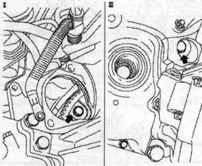
5.16 Torque converter bolt access holes (on the example of AF33): I. Engines Y20DTH and Y22DTR; II. Z32SE engine
17. Release fasteners (see illustrations) and disconnect the lines of the ATF cooling system. Close the AT holes with suitable plugs.
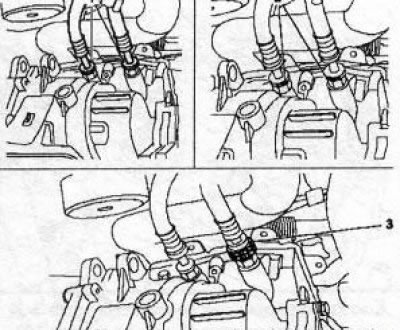
5.17a Removing clamps (2) fastening of cooling lines AT (transmission VT20-E): 1. Protective rings 3 Tool KM-J-4162-B
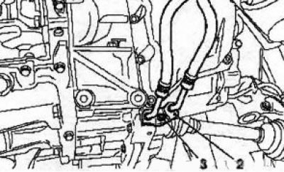
5.17b Nut (3) fastening lines (2) AT cooling systems (AF23 transmission)
18. Install the MKM-886-A tool on the box (see resist. illustration), by jacking it up
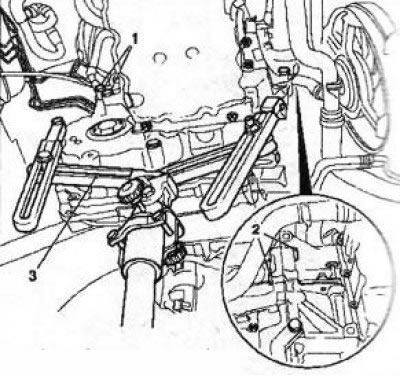
5.18 Installing the KM886-A fixture (3) (on the example of AF33): 1, 2. Transmission side bolts
Note: Before using the device, carefully read the instructions for its use.
Fasten the gearbox to the fixture, remove the lower bolts securing the gearbox to the oil pan.
19. Turn out the lower lateral bolts (see illustration 5.18) fastening the box to the engine, disconnect the box from the cylinder block, make sure that the transformer is separated from the drive disk, and lower it on the jack. Be careful not to drop the torque converter or damage the transmission components.
20. Fix the torque converter with a special tool (see resist. illustration).
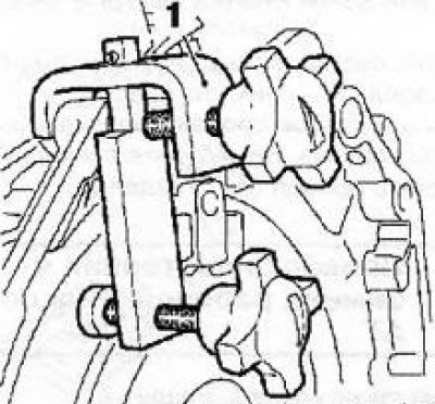
5.20 Installing the KM 6388 tool (1) for attaching the torque converter
21. Installation is made in the reverse order of removal. Don't forget to adjust the shifter (see section 2), as well as fill in fresh fluid and make an appropriate adjustment to its level (see Section 4).
Visitor comments