
OpelBook.ru
Cars AvtoVAZ Cars Mitsubishi Cars BMW Cars Mercedes Cars Nissan Cars Toyota Cars Chevrolet
English Русский
Български
Беларускі
Український
Српски
Hrvatski
Română
Polski
Slovenský
Magyar
 |  Sitemap  |  Contacts  |    


Main Astra Corsa Insignia Kadett Omega Vectra Zafira Others Articles
Frontera A (1991-1998, petrol) Frontera B (1998-2004) Ascona C (1981-1988) Vivaro A (2001-2014)
  • Main
  • Opel
  • Ascona C
  • Transmission
  • Automatic gearbox
  • Automatic transmission — removal and installation

Automatic transmission — removal and installation (Opel Ascona C)

            0

1. Removing the automatic transmission together with the engine is described in chapter 1. To remove just the box, you need to do the following.

2. Disconnect the wires from the battery and remove it.

3. Disconnect the ground bus from the box.

4. Disconnect the downshift cable from the carburetor and gearbox.

5. Disconnect the gear shift lever cable from the lever on the gearbox.

b. Remove the mounting clamp. Remove the lever from the box.

7. Unscrew the gear shift lever cable support bracket. There is no need to disconnect the cable from the bracket.

8. Loosen and remove the bolts securing the torque converter housing to the engine (see figure 6.51).

9. Unscrew the remaining bolt, remove the starter and tie it to the side with wire. There is no need to disconnect the wiring from the starter.

10. Disconnect the speedometer cable from the gearbox.

11. Remove the transmission fluid dipstick.

12. Raise the front of the car so that the box can be pulled out through the front.

13. Remove the front left wheel.

14. Connect the hoists to the engine or support it with a jack.

15. Disconnect the left rear fastening of the gearbox from the car body.

16. Disconnect the anti-roll bar from the lower left suspension arm.

17. Disconnect the left lower suspension arm support from the vehicle body (see chapter 10).

18. Disconnect the left drive shaft from the gearbox (see chapter 7).

19. Disconnect the right drive shaft from the gearbox (see chapter 7).

20. Disconnect the oil cooler tubes at the gearbox and plug their open ends (see figure 6.53).


21. Loosen the bolts and remove the torque converter cover (see figure 6.54).

22. Remove the bolts securing the drive disk to the torque converter. In order to get to each of the bolts, it is necessary to turn the drive disk (using a wrench placed on the crankshaft pulley bolt or the vibration damper bolt - these bolts must be replaced during the installation of the box). When removing each of the bolts, it is necessary to block the starter ring gear.

23. Unscrew the bolts and remove the left front cushion (see figure 6.56).

24. Loosen the exhaust pipe bracket bolts and turn the bracket upwards (see figure 6.57).

25. Pull out the dipstick tube (be prepared for some transmission fluid to spill out when doing this).

26. Support the box with a garage jack.

27. Working under the machine, disconnect the left rear support bracket from the machine body. Also remove 2 bolts from the engine support bracket (see figure 6.58 and 6.59).

28. Move the gearbox away from the engine so that it comes off the mounting pins and then lower it on the jack. Pull the box out from under the car through the front.

29. The box is installed in the reverse order. Please note the following points.

30. Before attaching the gearbox to the engine, check that the torque converter is fully engaged with the oil pump. To do this, measure size "A" (see picture), which should be equal to 9.00-10.00 mm. If a different value is obtained, turn the torque converter while simultaneously pressing on it with your hand (see figure 6.60).


31. Apply a small amount of molybdenum disulfide grease to the torque converter guide flange.

32. When securing the torque converter to the drive disk, align the white mark on the disk with the colored mark on the torque converter.

33. Connect the downshift cable first to the gearbox and then to the carburetor and adjust it as indicated in section 23.

34. Fill the gearbox with transmission fluid (see section 22).

35. Check that all bolts and nuts are tightened to the specified torque and that thread locking compound has been applied to the threads of the control arm support bolts.
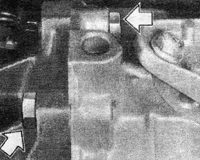
Figure 6.51. Torque converter housing to engine mounting bolts (shown by arrows)
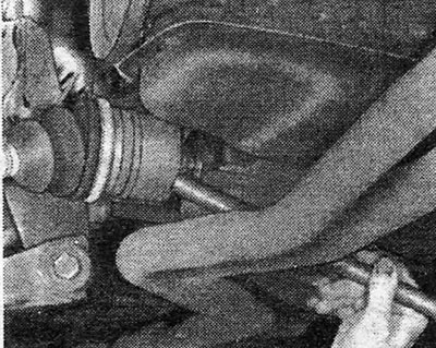
Figure 6.51. Torque converter housing to engine mounting bolts (shown by arrows)


Figure 6.52. Disconnect the right drive shaft from the gearbox using a punch
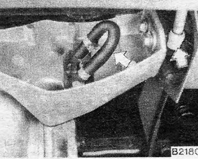
Figure 6.52. Disconnect the right drive shaft from the gearbox using a punch


Figure 6.53. Locations for disconnecting the oil cooler tubes at the gearbox (shown by arrows)
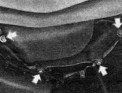
Figure 6.53. Locations for disconnecting the oil cooler tubes at the gearbox (shown by arrows)


Figure 6.54. Torque converter cover bolts (shown by arrows)
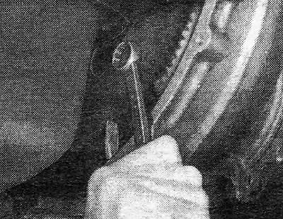
Figure 6.54. Torque converter cover bolts (shown by arrows)


Figure 6.55. Removing the bolts securing the torque converter to the drive disk
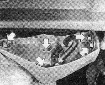
Figure 6.55. Removing the bolts securing the torque converter to the drive disk


Figure 6.56. Left front cushion bolts (shown by arrows)
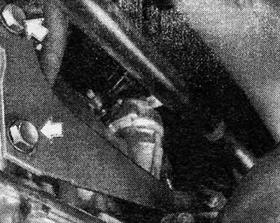
Figure 6.56. Left front cushion bolts (shown by arrows)


Figure 6.57. Bolts securing the exhaust pipe bracket to the gearbox (shown by arrows)

Figure 6.57. Bolts securing the exhaust pipe bracket to the gearbox (shown by arrows)


Figure 6.58. Left rear support bracket bolts (shown by arrows)
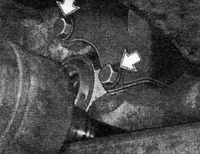
Figure 6.58. Left rear support bracket bolts (shown by arrows)


Figure 6.59. Bolts securing the transmission to the engine support bracket (shown by arrows)

Figure 6.59. Bolts securing the transmission to the engine support bracket (shown by arrows)
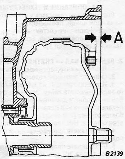

Figure 6.60. Checking the torque converter position: A = 9.0-10.0 mm.

Figure 6.60. Checking the torque converter position:
A = 9.0-10.0 mm.


This article is available at russian, bulgarian, belarusian, ukrainian, serbian, croatian, romanian, polish, slovak, hungarian
Checking the article: Kornev Georgy

Share information:

Previous articles
Opel Ascona C: Automatic gearbox
Next articles

Gear Shift Lever Cable — Removal, Installation and Adjustment
Downshift Cable — Replacement and Adjustment
Automatic transmission — routine maintenance
Automatic transmission — general description
Automatic transmission — specifications
Automatic transmission — fault diagnosis


See similar ones from other Opel car manuals:
▶ Automatic transmission repair — general information Opel Astra F (1991-1998, petrol)
▶ Automatic Transmission Fluid Replacement (ATF) Opel Corsa B (1993-2000)
▶ Automatic transmission Opel Kadett E (1984-1995)
▶ Automatic transmission Opel Omega A (1986-1993)
▶ Automatic transmission Opel Vectra A (1988-1995, petrol)
Link to this page in different formats

Visitor comments


No comments yet


How much will 23 + 43 =


Vivaro A (2001-2014) 
  • General information
  • User manual
  • Power unit
  • Petrol engine F4R
  • Diesel engine F9Q
  • Diesel engine G9U
  • Transmission
  • Clutch and drive shafts
  • Manual gearbox
  • Chassis
  • Front suspension
  • Rear suspension
  • Brake system
  • Body
  • Exterior
  • Interior
  • Electrical equipment
  • Heating and ventilation
  • Air conditioner
  • Equipment and devices
  • Electrical diagrams
Ascona C (1981-1988) 
  • General information
  • Maintenance
  • Power unit
  • Gasoline engines
  • Diesel engines
  • Cooling system
  • Fuel and exhaust system
  • Contact ignition system
  • Contactless ignition system
  • Transmission
  • Clutch
  • Mechanical gearbox
  • Automatic gearbox
  • Drive shafts
  • Chassis
  • Steering
  • Brake system
  • Car suspension
  • Body
  • Exterior
  • Interior
  • Doors and windows
  • Electrical equipment
  • Equipment and devices
  • Power devices
  • Electrical circuits
Frontera B (1998-2004) 
  • General information
  • User manual
  • Maintenance
  • Power unit
  • Petrol engines 2.2 l
  • Petrol engines 3.2 l
  • Diesel engines 2.2 l
  • Cooling system
  • Fuel system (petrol)
  • Fuel system (diesel)
  • Ignition system
  • Transmission
  • Clutch
  • Manual gearbox MUA5C
  • Automatic gearbox 4L30E
  • Chassis
  • Suspension and axles
  • Steering
  • Brake system
  • Body
  • Exterior
  • Interior
  • Doors, locks and windows
  • Heating and air conditioning
  • Electrical equipment
  • Power devices
  • Equipment and devices
  • Lighting and signaling
  • Electrical diagrams
Frontera A (1991-1998, petrol) 
  • General information
  • Introduction to guide
  • User manual
  • Maintenance
  • Power unit
  • Engine repair
  • Lubrication system
  • Cooling system
  • Power and exhaust system
  • Engine electrics
  • Transmission
  • Clutch
  • Mechanical gearbox
  • Cardan shafts
  • Chassis
  • Brake system
  • Front suspension
  • Rear suspension
  • Steering
  • Body
  • Repair and care
  • Electrical equipment
  • Equipment and devices
  • Electrical circuits
OpelBook.ru © 2017–2026 · Mobile version · · Sitemap: EN BG BY UA RS HR RO PL SK HU · Feedback · Site search
Astra F, petrol · Astra G, petrol · Astra G · Astra H · Astra J, petrol · Corsa B · Corsa C, petrol · Corsa C · Insignia A · Kadett D · Kadett E · Omega A · Omega B · Omega B2 · Vectra A, petrol · Vectra A · Vectra B, petrol · Vectra B · Vectra C · Zafira A, petrol · Frontera A, petrol · Frontera B · Ascona C · Vivaro A ·
We want your visit to be comfortable 🤝! We use cookies 🍪 to make that happen.