
AR25 transmission - general description
1. Beginning in 1990, 2.0 liter automatic transmission models were fitted with a new four-speed electronically controlled automatic transmission. This new AR25 drivetrain unit has three drive options: economy, sport and winter. Eco mode offers a way for normal driving, in which the vehicle is driven at relatively low engine speeds, combining acceptable driving speed with economical fuel consumption. The transmission is automatically set to economy mode when the ignition is turned on.
2. For high-speed driving, there is a sport mode, which is selected by a button on the top of the gear selector lever. When the transmission is in sport mode, an indicator lamp on the left side of the instrument cluster comes on. In this mode, the transmission engages gears with a higher gear ratio, with higher engine speeds, to provide maximum acceleration. Returning to the economy mode is done by simply pressing the selector button again.
3. Winter mode is selected using the button on the central console. When the winter mode is set, the LED indicator lights up. The car is moving in third gear. This limits torque on the drive wheels and allows the vehicle to drive safely on slippery roads. Winter mode can only be set when the selector lever is in the «D». Returning to economy mode is done by simply pressing the button on the lever again, or by moving the selector lever through «3» or «R». Note that the transmission will automatically exit winter mode and return to economy mode if the vehicle speed exceeds 80 km/h or if the downshift mechanism is pressed for more than 2 seconds.
AR25 Transmission - Maintenance
Checking the transmission fluid level
4. When checking the transmission fluid level, first drive the vehicle approximately 20 km to warm up the transmission to normal operating temperature. Park the vehicle on level ground. With the engine running and the brake applied, move the selector lever slowly from the «P» V «1», and then back to «P».
5. With engine idling and selector lever in position «P» remove the transmission fluid dipstick, wipe it clean, then reinsert it completely into the pipe. Remove the dipstick and note the fluid level. Repeat this procedure three times and choose the middle number, which will be the true transmission fluid level.
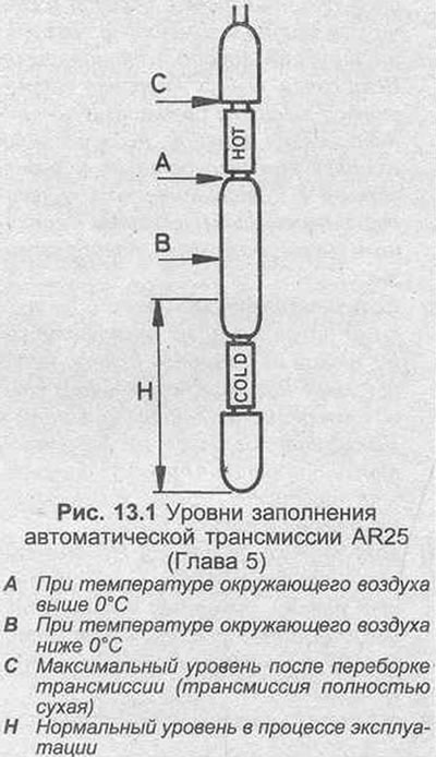
6. If the engine and transmission are at normal operating temperature, when the ambient temperature is above 0°C, the fluid level should be within the mark «NOT» on the dipstick (approximately 42 mm from the lower end of the dipstick). When the ambient temperature is below 0°C, the liquid level should be halfway between the marks «NOT» And «COLD» on the dipstick (approx. 32 mm from the lower end of the dipstick).
7. If necessary, top up with the specified fluid through the dipstick tube and recheck the fluid level as described above.
8. If the level is correct, install the dipstick and stop the engine.
Transmission Fluid Replacement
9. On an AR25 transmission, the fluid should be changed every 60,000 km or every 4 years, whichever comes first. It is also recommended to remove the large transmission pan and clean the transmission fluid filter while doing so. This will drain more transmission fluid and replace it accordingly (approximately only half of the transmission fluid is drained when only the sump drain plug is unscrewed), and all dirt will be removed from the filter and pan.
10. If you wish to change only the transmission fluid, this can be done as described in Chapter 2 of Section 6, referring to the Specifications at the beginning of this Section for the approximate amount of liquid. Finally, fill the transmission with the specified type of fluid, up to the correct level on the dipstick (see fig. 13.1), then start the car and check the level as described earlier in this Chapter. To also clean the filter element, proceed as follows.
11. Apply the handbrake, then jack up the front of the vehicle and support it on axle stands.
12. Place a container under the transmission pan, then remove the drain plug and let the fluid drain into the container.
Warning: If the vehicle has been recently run, the fluid will be extremely hot.
13. Check the drain plug seal and replace if necessary. After all the liquid has drained, wipe the threads clean and install the drain plug in the pan, clamping it with the tightening force regulated by the Specification.
14. Loosen and remove all sump mounting bolts, then carefully lower the sump away from the transmission. Be prepared for some fluid leakage. Note that the sump still contains a significant amount of transmission fluid. Drain the fluid from the pan into a container, then remove the gasket and discard it.
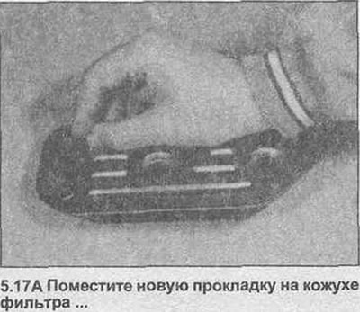
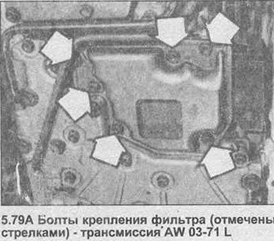
15. Turn off three bolts of fastening, then remove the filter from a reverse side of transmission together with a sealing lining. Throw away the pads; a new one must be used when installing.
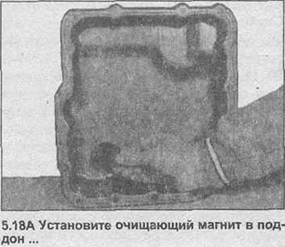
16. Clean the filter element in a solvent bath, then examine the element for signs of clogging or damage. If the filter element is leaky or clogged, the filter must be replaced. Remove the magnet inside the tray and clean the traces of metal particles on it; any large or small piece of metal indicates wear on the transmission components.
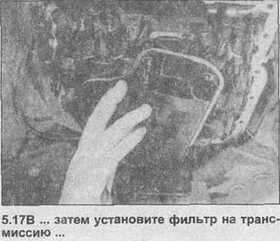
17. Check that the filter element is dry, then install a new gasket on the filter housing and attach the filter to the transmission. Check that the gasket is correctly installed, install the mounting bolts and tighten them with the tightening torque specified specification (photo).
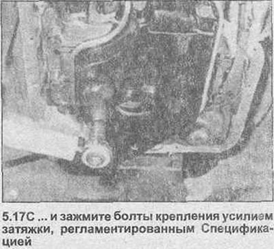
18. Check that the transmission sump and seal surfaces are clean and dry, then place a new gasket on the sump and install the magnet. Install the pallet on the transmission and tighten the fastening bolts with a tightening torque regulated specification (photo).
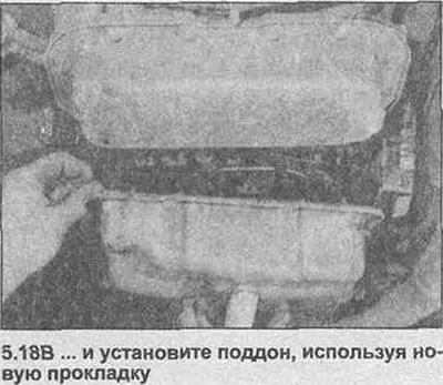
19. Lower the vehicle to the ground, then fill the transmission with the specified type of fluid, to the correct level on the dipstick (see figure 13.1); an approximate quantity is given in the Specifications at the beginning of this Section. Finally, start the car and check the fluid level as described earlier in this chapter.
AR25 transmission - removal and installation
Removing
20. Apply the handbrake and place the selector lever in the «N». Disconnect the negative battery terminal.
21. Remove the dipstick from the filler tube, then unscrew the dipstick tube bolt and gasket and remove the tube from the transmission.
22. Locate the transmission inhibitor switch wiring harness back to the wiring harness connector (which is fixed in the center of the partition of the engine compartment). Disconnect the connector and free the circuit breaker wiring harness from all appropriate mounting brackets and ties.
23. From inside the engine compartment, release the transmission breather hose from all mounting brackets and ties.
24. Block the rear wheels, then jack up the front of the vehicle and secure it on axle stands.
25. From the bottom of the vehicle, release the inhibitor switch wiring harness and breather hose from any remaining brackets.
26. On models without a catalytic converter, remove the exhaust manifold as described in Section 3, then unscrew the pipe fixing bracket and the heat shield. On models with a catalytic converter, remove the distribution pipe and converter using the information given in Chapter 3 from this Section, then remove the mounting bracket and heat shields of the catalytic converter.
27. Disconnect the two electrical wiring connectors on the left side of the gearbox housing and separate the electrical wiring from the transmission.
Note: When disconnecting wiring connectors, hold the bottom of each connector to prevent separation from the transmission.
28. Disconnect the speed sensor wiring from the mounting bracket and from the wiring connector.
29. Loosen and remove the four mounting bolts and remove the front cross member from under the vehicle.
30. Follow the steps described in paragraphs 9-17 Chapter 14 in Section 6.
31. Place a jack with a beam under the transmission and raise it until the weight of the transmission is selected.
32. Loosen and remove the nuts and bolts securing the rear cross member to the transmission and the four bolts securing the cross member to the bottom, then remove the cross member from below the vehicle.
33. With a jack under the transmission, loosen and remove the remaining bolts securing the transmission housing to the engine. Note the correct position of the bolts, and check that all necessary components have been disengaged.
34. With the bolts removed, move the jack and transmission towards the rear, freeing it from the pins. When the transmission is free, lower the jack and pull the unit out from under the vehicle, ensuring that the torque converter is properly positioned on the transfer shaft. Remove pins from transmission or engine.
Installation
35. The transmission is installed in the reverse order, taking into account the following points.
- a) Apply a small amount of heat resistant lubricant to the grooves of the transmission input shaft. Do not apply too much as this may contaminate the torque converter.
- b) Make sure the pins are correctly placed on the transmission before installation.
- c) Tighten all nuts and bolts to the torque specified in the Installation Specification.
- d) Before installing, coat the threads on the back of the crossbar-bottom mounting bolts with blocking compound.
- e) Check that the breather hose and wiring harness are properly installed and secured with all necessary clamps.
- f) Finally, fill the transmission with the specified type and amount of fluid and check the selector mechanism adjustment as described later in this Chapter.
Kickdown system (AR25 transmission) - general description and replacement of the switch
36. Unlike the earlier AW 03-71 L transmission, the AR25 transmission's lowering system is fully electronically controlled and does not have any drive cable. The system is started by a switch located under the throttle control pedal.
37. To remove the switch, disconnect the electrical wiring, then carefully remove the switch from the retainer using the lever. When installing, check that the switch is correctly placed on the retainer, then reconnect the wiring connector.
Select lever rod (AR25 transmission) - adjustment
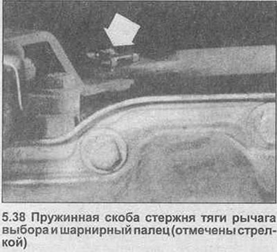
38. The select lever linkage can be adjusted using the information given in Section 6, Chapter 17 (photo). Finally, check the operation of the inhibitor switch and, if necessary, adjust as described later in this Chapter.
Selection lever (AR25 transmission) - removal and installation
Removing
39. Remove the central console assembly as described in Section 11.
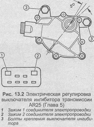
40. Apply the handbrake, then jack up the front of the vehicle and support it on axle stands.
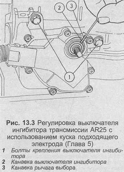
41. From the bottom of the car, release the spring clip, then remove the pivot pin and disconnect the link rod at the bottom of the select lever.
42. Inside the car, carefully drill out the five rivets securing the select lever cover to the body. Remove the selector lever and cover from the vehicle.
Installation
43. Remove all traces of sealant from the base of the casing of the selector lever and the car body.
44. Apply a suitable sealant to the back of the selector lever cover, then install the cover to the vehicle.
45. Secure the select lever cover with new rivets.
46. From the bottom of the vehicle, reattach the link rod to the base of the select lever, securing the pivot pin with a spring clip.
47. Install the central console as described in Section 11.
48. Check up adjustment of the mechanism of the selector and action of the switch, inhibitor as it is described in other place in this Chapter.
Inhibitor switch (AR25 transmission) - removal, installation and adjustment
Removing
49. Apply the handbrake and place the selector lever in the «N».
50. Locate the transmission inhibitor switch wiring harness back to the wiring connector (which is fixed in the center of the partition of the engine compartment). Disconnect the connector and free the circuit breaker wiring harness from all appropriate mounting brackets and ties.
51. Block the rear wheels, then jack up the front of the vehicle and secure it on axle stands.
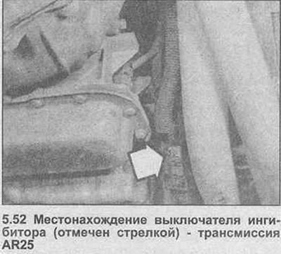
52. From the bottom of the vehicle, release the inhibitor switch wiring harness from any mounting brackets (photo).
53. Unfasten the lining of the inhibitor switch, then loosen and remove the nut securing the selector lever to the transmission, and separate the lever from the roller.
54. Turn off two bolts of fastening and pull off inhibitor.
Installation and adjustment
55. Before installing the switch, examine the shaft seal for signs of damage or oil leakage and replace if necessary. To replace the oil seal, gently pry up the oil seal with a small flathead screwdriver. Coat the lugs of the new oil seal with a thin, lubricating oil, then carefully fit over the end of the shaft and press into place in the transmission. If necessary, to seat the gland in place, use a pipe of suitable diameter, which is placed only on the outer edge of the gland.
56. Position the inhibitor, attach the roller, then install the two mounting bolts, finger-tight at this stage. Adjust the switch as follows. Before proceeding, temporarily install the selector lever on the shaft and check that the transmission is still in neutral («N»).
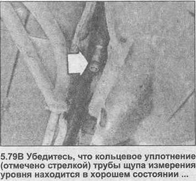
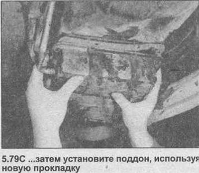
57. There are two ways to adjust the switch: mechanical and electrical. The electrical method is a much more accurate method but requires the use of a multimeter.
58. To adjust the switch electrically, connect a multimeter, set to the resistance measurement function, across terminals 1 and 2 of the switch wiring connector (see fig. 13.2). The transmission must be in neutral to ensure a closed circuit. Turn the switch slowly to determine the area where the switch trips. It should be within a sector with an angle of approximately 5°. Place the circuit breaker in the center of this area, then tighten the mounting bolts to the specified torque.
59. For mechanical adjustment of the switch, use a rod with a diameter of 2.0-2.3 mm. Place transmission in neutral position, rotate switch until grooves on switch and transmission selector lever line up and bar can be freely inserted (see fig. 13.3). Clamp the circuit breaker in this position, and tighten the fastening bolts with the torque specified in the Specification. Check that the grooves are still properly aligned, then remove the rod.
60. When the inhibitor switch is properly adjusted, place the selector lever on the transmission shaft and tighten the lock nut to the specified torque.
61. Feed the switch wiring into the engine compartment.
62. From inside the engine compartment, reconnect the inhibitor switch harness connector and secure the harness with new clamps.
63. Check the adjustment of the selector mechanism as described in Section 6, Chapter 17, then check that the inhibitor switch is working properly.
64. Install the inhibitor switch trim and lower the vehicle to the ground.
Electronic transmission control device (AR25 transmission) - removal and installation
Removing
65. The electronic control device is located under the hood (behind the left end of the plastic water baffle).
66. To remove the block, open the hood, then remove the seal from the left end of the water baffle. Carefully lift up the water baffle to access the control box (photo).

67. Turn off a bolt of fastening and get the control unit, disconnecting a connector of electroconducting.
Installation
68. Installation is the reverse procedure of removal.
Sport mode switch (AR25 transmission) - removal and installation
Removing
69. Using a small flathead screwdriver, carefully pry off the mechanism indicator panel trim and remove from the select lever.
70. Remove the single fixing screw, then separate the panel from the central console. Remove the lamp socket from the panel and lift the panel away from the selector lever.
71. Feed the sport mode switch wiring harness through the base of the select lever.
72. Carefully unsolder the two wires and remove the switch.
Installation
73. Installation is the reverse procedure of removal. Make sure the wires are securely soldered to the switch. Check the operation of the switch before installing the panel.
Winter mode switch (AR25 transmission) - removal and installation
Removing
74. Unfasten the middle panel of the console, and remove it from the center console, disconnecting the connector (And) switch wiring.
75. Press the switch mounting rods and pull the switch out of the casing.
Installation
76. Installation is carried out in the reverse order.
Transmission fluid filter (transmission AW 03-71L) - cleaning
77. When changing the transmission fluid in the specified interval, it is also recommended to remove the sump and clean the transmission filter. This will also allow more fluid to be drained and replaced and the composition of the used fluid to be examined.
78. To clean the filter, first follow the steps described in paragraphs 13-15 Chapter 2 of Section 6.
79. Remove the pallet and clean the transmission GG filter, as described in paragraphs 1418 of this Chapter, given that the filter is fixed with six bolts and that there are two magnets in the pallet. Also, before installing the sump, examine the dipstick tube O-ring for signs of damage and replace if necessary (photo).
80. Finally, fill the transmission and check the fluid level as described in Section 6, Chapter 2.
Visitor comments