
General description
1. Since 1990, all 2.0 liter models are equipped with the Motronic M1.5 fuel injection system, instead of the ML4 system installed on earlier models. Both systems are very similar in how they operate, the only significant change in the M1.5 system being the installation of a throttle potentiometer instead of the throttle switch used in the early ML4 system. The advantage of a potentiometer is that it provides information to the control unit about the exact position of the throttle, and not only that. valve is open or closed. This allows you to more accurately adjust the quality of the fuel / air mixture in various engine operating modes.
2. Starting in 1990, 2.0 liter models were also equipped with a catalytic converter. These models have an engine code C20NE and are equipped with a closed three-way system with a catalytic converter to reduce the amount of harmful emissions in the exhaust gases. The system is controlled by a lambda sensor, which is screwed into the distribution exhaust pipe. The tip of the lambda sensor is sensitive to oxygen and provides the fuel injection system control unit with constant feedback on the state of the exhaust gases. This allows the control unit to fine-tune the amount of fuel supplied to the engine, calculate the required fuel/air ratio, and thereby ensure maximum efficiency. The tip of the Lambda sensor also has a built-in heating element, which is controlled by the control unit. When the engine is cold, the control unit supplies electricity to the heating element for heating the Lambda sensor, which in turn heats the exhaust gases passing through the sensor. The heated exhaust gases quickly bring the catalytic converter up to normal operating temperature, at which it operates efficiently.
3. On models with a catalytic converter, a fuel vapor control system is installed. This prevents the release of fuel vapors into the atmosphere. With the ignition off, vapors from the fuel tank are fed to the carbon filter where they are absorbed. When the engine is started, the electronic control device opens the purge traction relay valve, and fuel vapors are supplied to the intake manifold and mixed with fresh air. This cleans the carbon filter.
4. Unless otherwise noted, the procedures to be followed on these later models are the same as for the 2.0 liter models in Section 3.
Checking and Adjusting the Mixture - Catalyst Models
On models with a catalytic converter, the fuel/air mixture is monitored by a lambda sensor and therefore does not need any adjustment. However, the performance of the catalytic converter system should be checked periodically using a calibrated exhaust gas analyzer. If the CO level in the exhaust pipe is too high, the entire fuel injection system and ignition system should be fully checked using diagnostic equipment.
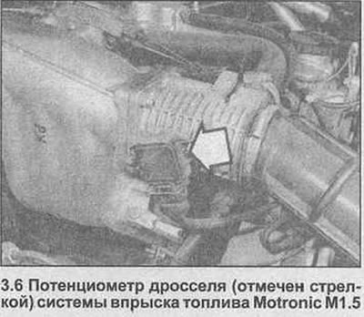
Throttle valve potentiometer - removal and installation
6. The throttle potentiometer can be removed and replaced using the throttle switch information given in Section 3, Chapter 25, ignoring the remark regarding the adjustment of the switch (photo). Throttle potentiometer adjustment is not necessary.
Lambda sensor (models with catalytic converter) - removal and installation
Note: The lambda sensor must be unscrewed from the exhaust manifold when the engine is at normal operating temperature. The sensor is very sensitive and will not work if it is damaged, if there is a power failure, or if any cleaning materials or solvents are used in its processing.
Removing
7. Warm up the engine to normal operating temperature, then shut it off. Apply the handbrake, jack up the front of the vehicle and support it on axle stands.
8. Be careful not to burn yourself on the hot exhaust pipe when disconnecting the sensor wiring connector and releasing the wiring from the mounting brackets.
9. Carefully unscrew the Lambda sensor and remove it from the exhaust system together with the seal.
Installation
10. If you are installing the original lambda sensor, remove all traces of anti-lock threads and coat with special lubricant (number 19 48 602 parts) sensor thread. If the specified lubricant is not available, lubricate with a good quality high temperature anti-seize compound, (type Duckhanis Copper 10). Please note that new Lambda sensors are already coated with thread lubricant. Check the gasket for signs of damage and replace if necessary.
11. Install a sealing gasket on the end of the lambda sensor, then screw the sensor into the distribution pipe and tighten with a tightening torque specified specification.
12. Check that the wiring is properly routed and reconnect the wiring connector and secure the wiring with all necessary mounting brackets.
13. Finally, check that the electrical wiring is out of danger of contact with the exhaust system, then lower the car to the ground.
An exhaust manifold (models with catalytic converter) - removal and installation
14. On these models, the exhaust manifold can be removed and reinstalled as described in Chapter 29 of Section 3, noting that it is necessary to disconnect the lambda sensor wiring connector and remove the wiring from the mounting brackets before disconnecting the distribution pipe. When installing, reconnect the wiring connector and check that the wiring is correctly positioned and secured with all necessary mounting brackets.
Exhaust system (models with catalytic converter) - general description, removal and installation
Note: The catalytic converter is a fragile element that can be easily damaged - all parts of the system are removed, being careful not to hit the tools during processing.
15. On these models, the exhaust system is very similar to the equipment of the 2.0 liter model, except that it consists of four parts - the fourth part is directly a catalytic converter installed between the distributor and intermediate pipe.
16. The system can be removed and reinstalled using the information given in Chapter 30 of Section 3, noting that before removing the entire system or distribution pipe, it is necessary to disconnect the Lambda sensor wiring connector and release the wiring from the mounting brackets, or directly remove the sensor, as described earlier in this Chapter. When installing, install the sensor as described earlier in this Chapter and/or check that the wiring is securely fastened with all necessary mounting brackets and is out of danger of contact with the exhaust system (where applicable).
Catalyst - General Description and Precautions
17. The catalytic converter is a reliable and simple device that does not need any maintenance, but there are some facts that the car owner must be aware of in order for the converter to function properly throughout its life.
- a) Do not use leaded gasoline in a car with a catalytic converter - lead coats precious metals, reduces conversion efficiency, and eventually destroys the converter.
- b) Always keep the ignition and fuel system in good condition - especially check the air filter element, fuel filter and spark plugs and replace according to the manufacturer's instructions. If the air/fuel mixture becomes too rich due to neglected replacement, unburned excess fuel will enter and burn in the catalytic converter, overheating the element and eventually destroying the converter.
- c) If the engine is misfiring, do not operate such a vehicle (or at least as little as possible), until the damage is repaired. A misfire allows unburned fuel to enter the converter, causing overheating as noted above in paragraph (b).
- d) When starting the engine, do not push - or tow the vehicle - this will also introduce unburned fuel into the catalytic converter and cause overheating, see page 100. (b).
- e) do not turn off the ignition at a high engine speed. If the ignition is turned off at high idle, unburned fuel will enter the catalytic converter (very hot), with a possible risk of ignition on the element and damage to the transducer.
- j) DO NOT use fuel with engine oil additives - they may contain substances harmful to the catalytic converter.
- g) DO NOT continue to operate the vehicle if the engine is consuming oil. A characteristic sign of oil getting into the fuel is blue smoke - unburned carbon particles clog the converter channels and reduce efficiency; The element will overheat during extended use.
- h) Remember that the catalytic converter operates at very high temperatures, so the heat shields on the underside of the car and body will get hot enough to ignite any combustible materials that may get on them. Therefore, do not park your vehicle on dry, long grass or a pile of leaves.
- i) Remember that the catalytic converter is fragile - do not hit it with tools during operation. When traveling from outside, do not drive the car in ruts, road humps, etc., so as not to damage the exhaust system.
- j) In some cases, especially when the vehicle is new, there may be a sulphurous smell (rotten eggs) from the exhaust. This is the case for most catalytic converters found in vehicles and due to the small amount of sulfur found in some gasolines, it reacts with hydrogen in the exhaust to produce hydrogen sulfide gas (H2S); this gas is poisonous, but not produced in sufficient quantities to cause a problem. If the car has driven a few thousand miles, the problem should go away by) The catalytic converter, with good maintenance, should work effectively for 90,000-160,000 km. The CO level should not exceed the norm, if this is not the case, it is necessary to replace the converter.
Carbon filter (models with catalytic converter) - removal and installation
Removing
18. The coal filter is installed on the bulkhead of the engine compartment. To remove it, loosen the hose clamps and disconnect the hoses from the casing, noting their correct position. Loosen and remove the top cowling hanger clamp bolt, then remove the clamp and remove the cowl from the engine compartment.
Installation
19. Installation is carried out in the reverse order.
Purge valve (models with catalytic converter) - removal and installation
Removing
20. Locate the outlet hose from the charcoal filter (mounted on the bulkhead of the engine compartment) to the purge valve. Mark their correct installation position, loosen the mounting brackets and disconnect the hoses from the valve.
21. Disconnect the valve wiring connector, then unscrew the fastening bolt and remove the valve from the engine compartment.
Installation
22. Installation is the reverse procedure of removal. Check that the vacuum hoses are correctly installed and securely fastened with mounting brackets.
Visitor comments