
Fuel Injection Systems - Later Models
Bosch L3 Jetronic system - description
1. The Bosch L3 Jetronic fuel injection system has been installed on models with an engine capacity of 1.8 liters since 1987.
2. This system is based on the L3 type which was used previously, but has a digital control system rather than the analogue one used in the LE type. The L3 control device is located inside the engine compartment as part of the air flow sensor design.
Bosch Motronic system - description
3. The Bosch Motronic system is installed on all models with an engine capacity of 2.0 liters.
4. This system is a further development of the L3 Jetronic system used on earlier models and differs from it in that it controls combustion and ignition delay. By combining control of the fuel delivery and ignition systems, the engine greatly improves its performance in terms of power, efficiency and reliability. Other advantages are that there is no need for maintenance of this system, as well as the fact that it is equipped with a built-in self-diagnostic device, and if any malfunction occurs in it, information about this will be displayed on the instrument panel, where the corresponding indicator light will light up (when turned on by a specialist). Thus, any malfunction in the system can be quickly detected and eliminated.
5. Since the Motronic control unit also regulates ignition timing, there is no need to install appropriate mechanical and vacuum equipment, and the ignition distributor is used only as a high voltage distributor. The flash point on Motronic equipped models is determined by engine temperature, inlet air temperature, throttle opening and engine speed.
b. An inductive pulse sensor is installed on the side of the cylinder block, and the sensor disc is mounted on the crankshaft. As the teeth of the touch disk contact the pulse sensor during engine rotation, the air gap between them changes in accordance with the engine speed, and this signal is then transmitted to the control device. This information, obtained from the pulse sensor, together with the engine temperature, also ensures that the control unit adjusts the ignition timing.
7. The Motronic system also includes an idle speed control device. This device is mounted between the camshaft cover and the throttle body, and its function is to regulate the flow of air passing through the throttle when the engine is idling. The air flow is adjusted as needed by an electric motor. The idle speed regulator is adjusted automatically as needed, in accordance with the signals received from the control device. Therefore, manual idle speed adjustment is not possible.
8. This monitoring device is located on the side of the flywheel on the driver's side, behind the side decorative panel.
L3 and Motronic systems - general information
9. Except for the following notes, all service and repair procedures for both systems will be the same as described for the earlier L3 Jetronic fuel injection systems, in Chapter 3. Precautions mentioned in Section 21 Chapter 3 are also required for later models, and in addition note the following:
- (A) All fault information recorded in the integrated diagnostic system will be erased when the battery is disconnected;
- (b) Do not short circuit between the ignition coil terminal 1 and ground, and do not allow it to touch the positive terminal of the battery, otherwise the monitor will be damaged;
- (With) When installing a safety alarm on vehicles equipped with a Motronic fuel injection system, the alarm relay must not receive interference from other electrical sources (ignition wires, etc.)
Idle and mixture (L3 and Motronic systems) - adjustment
10. Idle speed and mixture composition can only be adjusted in the case of L3 Jetronic systems. As noted earlier, the idle speed in Motronic systems is adjusted using a special device, and it cannot be adjusted in any other way. The level of CO content in the exhaust is also not manually adjusted, but is completely controlled by the device.
11. Before proceeding with the steps below, make sure the ignition system is in good condition, the air cleaner is clean, and the engine is in good working order.
12. With the engine running and at normal operating temperature, connect an accurate tachometer according to the manufacturer's instructions.
13. Allow the engine to idle at the speed specified in the Specifications. If the need for adjustment is apparent, turn the idle speed adjustment screw on the throttle body as needed until the desired speed is achieved (see photo 5.13).
Photo 5.13 Idle speed adjustment screw (L3 Jetronic)
14. To check the mixture (CO level), connect the device - gas analyzer, in accordance with the manufacturer's instructions. With the engine running at the specified speed, take readings on the CO content and compare them with the required ones.
15. If adjustments are necessary, remove the black protective cap from the control device on the air flow sensor, and turn the adjustment screw as necessary to obtain the required results (see photo 5.15).
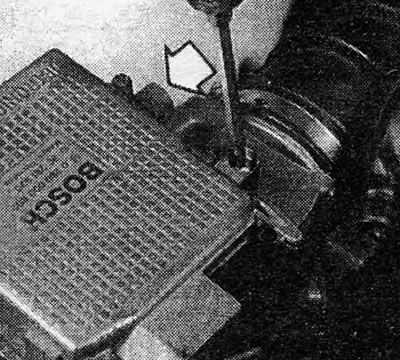
Photo 5.15 Mixture adjustment screw - indicated by arrow (L3 Jetronic)
16. Upon completion of the adjustment, re-adjust the idle speed if necessary.
17. If it is impossible to bring the CO level into compliance with the requirements specified in the Specifications, a malfunction in the injection system or severe engine wear should be suspected.
Fuel injection system parts (L3 and Motronic) - removal and installation
18. The removal and installation procedures given in Chapter 3 for LE Jetronic systems can also be applied in this case, with the exception of the differences described below.
Damper valve housing
19. Using a small screwdriver, remove the retaining clip and release the throttle cable from the binding (see photo 5.19 A and B).
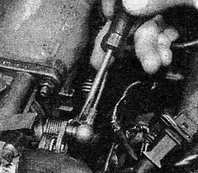
Photo 5.19 A Remove the securing spring clip...
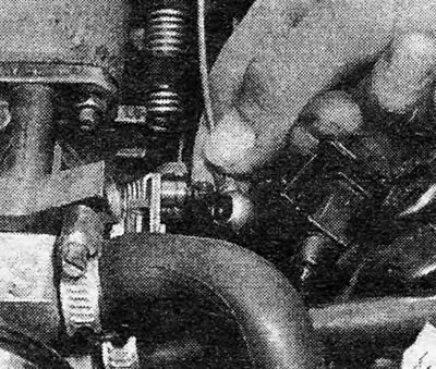
Photo 5.19 V... and disconnect the fastening of the end of the damper cable
20. Loosen the hose clamps and disconnect the tubes between the throttle valve housing and the air flow sensor (see photo 5.20).
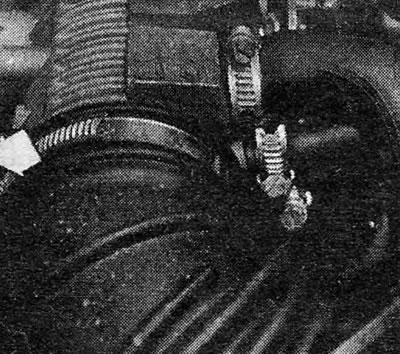
Photo 5.20 Loosen the flexible hose clamp (indicated by arrow)
21. Disconnect the auxiliary air valve hose, or idle air control valve hose, crankshaft housing ventilation hose, and coolant hoses from the throttle valve housing connections (see photo 5.21). If the engine is warm, relieve pressure in the cooling system by carefully removing the reservoir cap before disconnecting the coolant hoses. Close the hoses after disconnecting to minimize coolant loss.
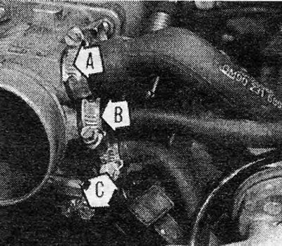
Photo 5.21 Disconnect the auxiliary air valve hose (A), crankshaft housing ventilation hose (IN) and cooler hoses (WITH)
22. Disconnect the electrical connector from the damper valve switch located at the rear of the housing.
23. When removing the damper valve housing itself, unscrew the four nuts and remove the housing.
24. If you are removing the damper valve housing along with the piping inlet, you must also remove the components described below.
25. Disconnect the brake booster hose and the auxiliary air valve hose from the pipeline.
26. Disconnect and close the fuel hoses from the fuel distributor. Also unscrew the bolt and release the fuel hose clamp from under the damper valve housing (see photo 5.26)
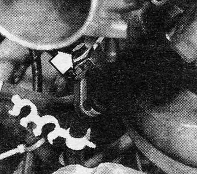
Photo 5.26 Fuel hose clamp mounting bolt (indicated by arrow)
27. Disconnect the choke cable from the support bracket by releasing the E-clip from the groove in the outer cable (see photo 5.27)
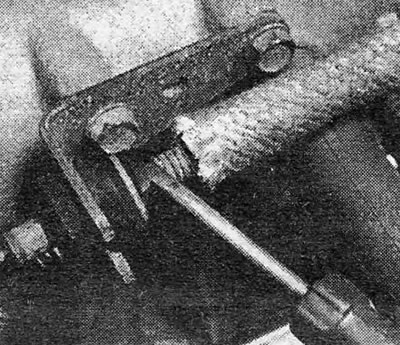
Photo 5.27 Release the E-shaped clamp of the damper cable
28. Release the electrical wiring by disconnecting all additional plugs and connections and ground wires. These include:
- (A) Air flow sensor
- (b) Coolant temperature sensor
- (V) Fuel injectors
- (G) Auxiliary air valve
- (d) Idle speed control (Motronic)
- (e) Grounding the camshaft cover
29. Unscrew the pipeline inlet mounting screws and remove the damper valve casing and the pipeline inlet together. Remove the inlet gasket.
30. Reinstallation is carried out by performing the above steps in reverse order.
Damper valve switch
31. The procedure is exactly the same as described in Chapter 3, only note that the switch is located on the opposite side of the throttle valve housing, next to the motor (see photo 5.31).
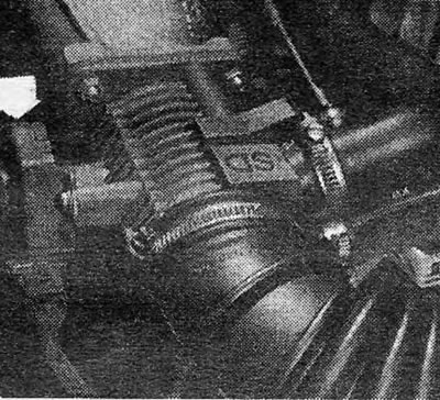
Photo 5.31 Position of the damper valve switch (indicated by arrow)
Fuel injectors
32. Disconnect the battery ground cable and perform the following operations with the engine cold and in a well-ventilated area.
33. Remove the two bolts securing the damper cable support bracket to the pipeline.
34. Disconnect the brake booster vacuum hose and auxiliary air valve hose from the line.
35. Disconnect the electrical wiring plugs from the fuel injectors (see photo 5.35).
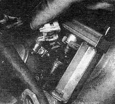
Photo 5.35 Disconnect the fuel injector wiring plugs
36. Using a small screwdriver, remove the clamp securing the fuel distributor tube to the injectors (see photo 5.36).
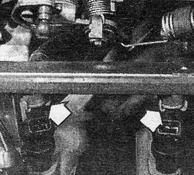
Photo 5.36 Disconnect the fuel distributor tube mounting clamps (indicated by arrows)
37. Unscrew the four fastening bolts of the fuel distributor tube and remove the tube, holding it very straight, lifting it up from all injectors.
38. Remove the fuel injectors from their places in the pipeline.
39. Reinstallation is carried out by performing the above steps in reverse order, do not forget to replace the 0-ring injector gasket if it shows even the slightest signs of damage.
Monitoring device L3 Jetronic
40. Remove the air flow sensor as described in Chapter 3.
41. Unscrew the four bolts and remove the control device cover.
42. Reinstallation is carried out in the reverse order.
Motronic monitoring device
44. Remove the decorative panel on the lower side of the driver's seat.
45. Disconnect the electrical wiring plug by pressing the retaining clip to the side.
46. Unscrew the three screws and remove the control device.
47. Reinstallation is carried out in the reverse order.
Idle speed regulator (Motronic)
48. Disconnect the electrical wiring plug from the end of the idle speed control (see photo 5.48).
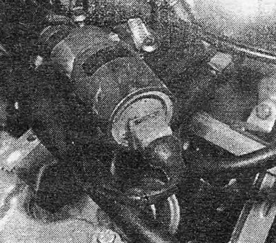
Photo 5.48 Location of the idle air control wiring
49. Loosen the hose clamps, disconnect all air hoses and remove the regulator.
50. Reinstallation is carried out in the reverse order.
Refined fuel (lead free) - general information
51. 1.8 and 2.0 liter engines equipped with L3 and Motronic fuel injection systems have an adjusting plug for the octane number of gasoline in the ignition system wiring (see photo 5.51). This plug, located on the right side of the engine compartment, is pre-set to give optimum engine output and maximum efficiency when running on 98 RON petrol (four stars).
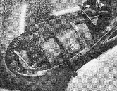
Photo 5.51 Fuel octane adjustment plug
52. To operate the engine on high-octane lead-free fuel, the position of the plug must be such as to modify the timing characteristics of the ignition system. This is necessary in order to avoid detonation (knocking and jolting) when accelerating and possible engine damage during use.
53. To install the octane plug, open its locking clip, disconnect the plug and turn it 180° (half a turn), and then reconnect it.
54. If, after adjustment, the octane number of the fuel used is so low that there is a constantly noticeable knocking sound, consult a specialist.
55. When using regular gasoline again, fill the fuel tank with it, but do not immediately change the octane plug as a mixture of the two fuels will initially cause an octane rating lower than that required for 98 RON.
Pipeline inlet (L3 and Motronic systems) - removal and installation
56. Removal and installation of the intake manifold system on engines equipped with L3 and Motronic systems is described as part of the process of removing and installing the throttle valve cover, in paragraphs 19 to 30 inclusive.
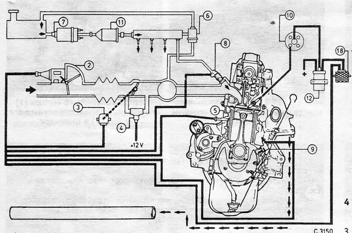
Figure 13.2. Diagram and details of the Bosch L3 Jetronic fuel injection system *2. Air flow sensor and control device; 2. Damper valve switch; 4. Auxiliary air valve; 5. Coolant temperature sensor; 6. Fuel pressure regulator; 7. Fuel pump; 8. Fuel injector; 9. Inductive pulse sensor; 10. Ignition distributor; 11. Fuel filter; 12. Ignition coil; 18. HEI ignition trigger
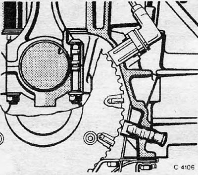
Figure 13.3. Inductive pulse sensor location - Motronic
Visitor comments