
Throttle body
2. Disconnect the distributor vacuum hose from the throttle body (see photo).
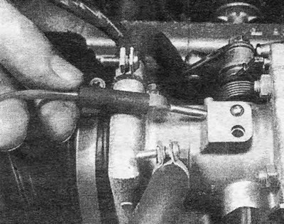
Photo 25.2. Disconnect the distributor vacuum hose from the throttle body.
3. Disconnect the crankcase ventilation hose (see photo).
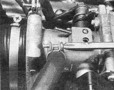
Photo 25.3. Disconnect the crankcase ventilation hose from the throttle body.
4. Disconnect the cooling system hoses from the throttle body (see photo) and squeeze them. If this work is performed on a hot engine, you should first remove the pressure from the system by carefully unscrewing the expansion tank plug.
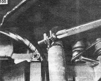
Photo 25.4. Disconnect the cooling system hoses from the throttle body. The second hose is located below.
5. Loosen the clamps and disconnect the flexible tube connecting the throttle body to the air flow sensor (see photo).
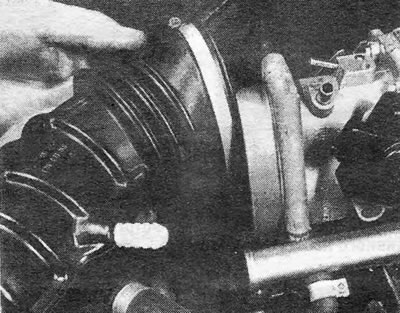
Photo 25.5. Disconnect the flexible tube from the throttle body.
6. Disconnect the electrical plug from the throttle switch.
7. If you are removing just the throttle body, disconnect the throttle valve actuator at the ball joint, remove the mounting nuts, and remove the throttle body from the intake manifold.
8. If you want to remove the throttle body along with the intake manifold, you should also disconnect the following.
9. Disconnect the brake servo cylinder hose and auxiliary air hose from the manifold (see photo).
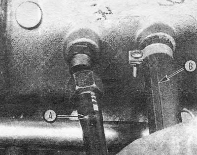
Photo 25.9. Disconnect the brake servo cylinder hose (A) and auxiliary air hose (IN).
10. Disconnect the fuel hoses from the distribution pipes and plug them. Please note that the hose with the white belt is located closest to the generator. When connecting these hoses, you need to ensure that they are installed correctly.
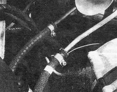
Photo 25.10. Fuel hoses in the engine compartment.
11. Disconnect wiring, electrical plugs and wires "masses". This includes:
- A. air flow sensor plug
- b. coolant temperature sensor
- V. fuel injectors
- d. throttle switch
- d. auxiliary air valve
- e. cam cover ground screw.
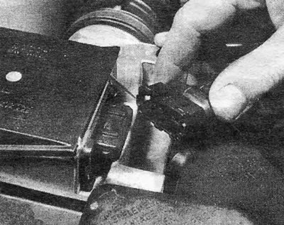
Photo 25.11A. Disconnecting the plug from the air flow sensor.
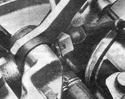
Photo 25.11B. Location of the coolant temperature sensor plug.
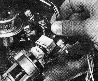
Photo 25.11С. Disconnecting the plug from the fuel injector.
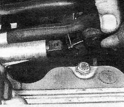
Photo 25.11D. Disconnecting the plug from the auxiliary air valve.
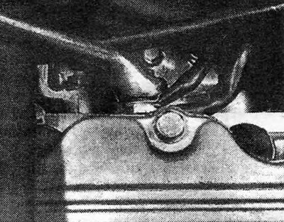
Photo 25.11E. Cam cover grounding point.
12. Disconnect the throttle cable from the throttle body. The ball joint at the end of the cable is secured with a spring clip. The end of the outer cable is secured to its bracket using an E-shaped clamp that fits into a groove at the end of the cable. This system allows you to adjust the cable tension (see photos).
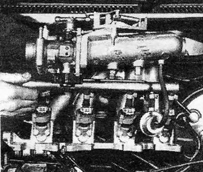
Photo 25.12A. Removing the throttle body along with the intake manifold.
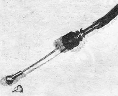
Photo 25.12V. Engine end of the throttle cable.
13. Remove the nuts securing the intake manifold. The bottom nuts are difficult to get to, so a small socket or socket wrench will help.
14. Remove the throttle body along with the intake manifold. Tear off the manifold flange gasket - during assembly it must be replaced with a new one (see photos).
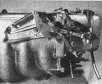
Photo 25.14A. Throttle body. The throttle valve drive mechanism is visible.
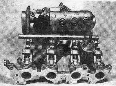
Photo 25.14B. Throttle body and intake manifold removed.
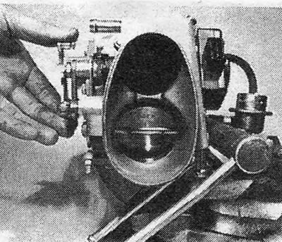
Photo 25.14С. Throttle body. The throttle valves are visible.
15. Install the throttle body in the reverse order. Be careful when connecting the wiring: injector No. 4 is closest to the flywheel housing.
Throttle switch
16. Disconnect the 3-pole plug from the switch (see photo).
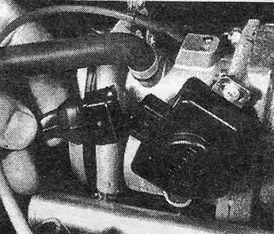
Photo 25.16. Disconnecting the plug from the throttle switch.
17. Unscrew the 2 mounting screws and remove the switch from the throttle valve axis.
18. Install the switch in the reverse order. Adjust the switch as indicated in section 24.
Fuel pump
19. The fuel pump is located at the rear of the fuel tank on the right side (see photo). Before removing the pump or related parts, disconnect the negative battery cable.
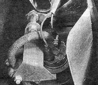
Photo 25.19. Fuel pump location.
20. Clamp the fuel hoses on both sides of the pump to avoid fuel leakage when disconnecting them. Disconnect the hoses.
21. Unscrew the clamping screws securing the pump and pull the pump out of its rubber casing. While pulling out the pump, simultaneously disconnect the electrical plug from it (see photos).
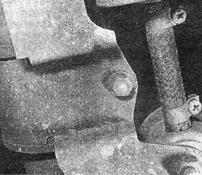
Photo 25.21A. Fuel pump mounting bolt.
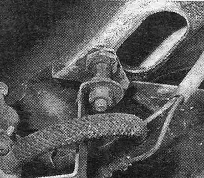
Photo 25.21B. Bolt securing the fuel pump and damper diaphragm.
22. Alternatively, you can remove the pump along with the filter and damper membrane, if you first unscrew the nuts of the mounting bracket and pull the assembly out of its rubber fasteners.
Fuel filter
23. The fuel filter is located next to the fuel pump (see photo).
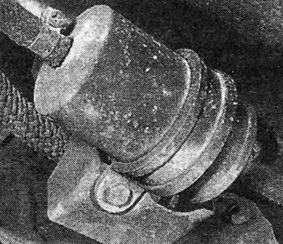
Photo 25.23. Fuel filter. The fastenings and the hose connection point are visible.
24. Clamp the fuel hoses to avoid fuel leakage when disconnecting them. Disconnect the hoses and remove the filter.
25. Filter installation is done in reverse order. Observe the mark "AUS" (outward), indicating the direction of fuel flow. If desired, you can similarly remove the damper membrane installed on the same bracket between the pump and filter (see photos).
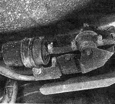
Photo 25.25A. Location of the fuel filter and damper membrane.
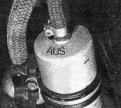
Photo 25.25V. A mark on the filter indicating the direction of fuel flow.
Fuel injectors
26. Check that the engine is cold (to eliminate the possibility of fuel ignition).
27. Loosen the hose clamps and pull the injector hoses off the distribution pipe nozzles (see photo). Try to collect any spilled fuel if possible.
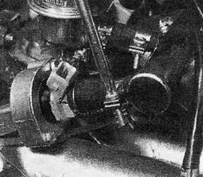
Photo 25.27. Loosen the hose clamp securing it to the distribution pipe.
28. Disconnect the plug from the desired injector.
29. Unscrew the mounting bolts and pull the nozzle out of the holder, taking care not to damage the needle valve (see photo).
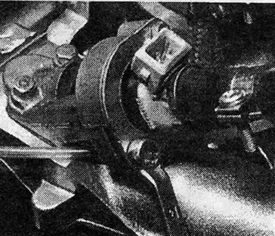
Photo 25.29. Removing the fuel injector.
30. Install the injectors in the reverse order. Replace the O-rings if their condition is questionable.
Air flow sensor
31. The air flow sensor is located between the air cleaner and the throttle body.
32. Disconnect the electrical plug from the sensor. Loosen the clamp and disconnect the rubber tube (see photo).
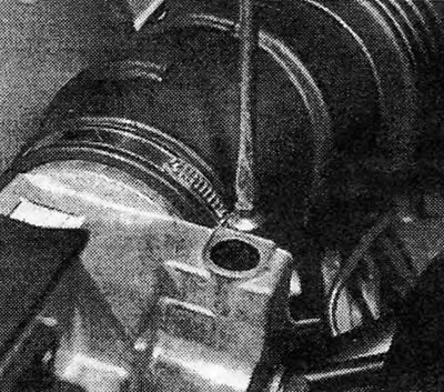
Photo 25.32. Disconnect the rubber tube from the air flow sensor.
33. Loosen the fork clamps and remove the air flow sensor along with the upper part of the air cleaner.
34. Remove the bolts and remove the sensor from the air cleaner housing (see photos).
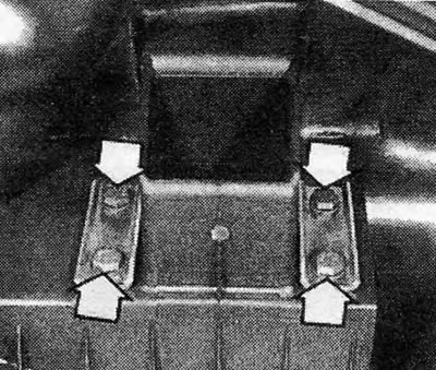
Photo 25.34. Bolts securing the air flow sensor (shown by arrows).
35. Check that the sensor flap valve moves freely without jerking or jamming.
Control block (LE Jetronic system)
36. The control unit is located on the side of the front footwell.
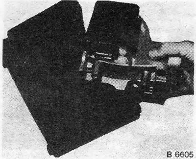
37. Remove the trim panel on the side of the footwell (passenger seat) (see photos).
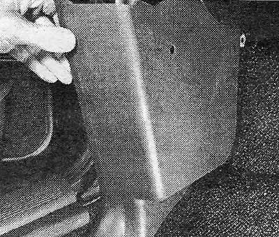
Photo 25.37A. Remove the side panel of the footwell in front of the passenger seat...
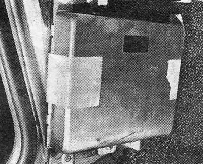
Photo 25.37B....to access the LE Jetronic control unit.
38. Push the spring clip aside and disconnect the electrical plug from the unit.
39. Remove 3 screws and remove the control unit.
Coolant temperature sensor
40. This sensor, located next to the generator, is optional and is installed on models with a fuel injection system (see Fig.3.57).
41. Partially drain the coolant (3 liters should be enough).
42. Disconnect the electrical wiring and unscrew the sensor.
43. Install the sensor in the reverse order.
44. Add coolant to the system and bleed it (see chapter 2).
Auxiliary air valve
45. This valve is located on the side surface of the camshaft housing.
46. Disconnect the electrical plug from the valve (see photo).
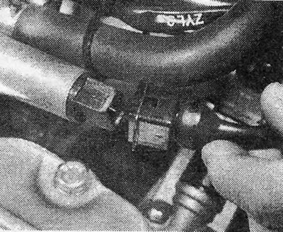
Photo 25.46. Disconnect the plug from the auxiliary air valve.
47. Disconnect the hoses. Unscrew the 2 mounting bolts and remove the valve.
48. The serviceability of the valve can be checked by monitoring the operation of the locking plate. When the valve is cold, the plate must be open; when it is hot, (connect the valve to a 12 V battery) — closed.
49. Install the valve in the reverse order.
Command relay
50. This relay is located on the front mudguard cup (see photo).
51. Unscrew the mounting bolt, disconnect the electrical plug and remove the relay (see photo).
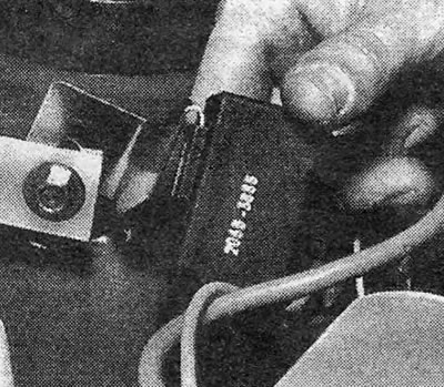
Photo 25.51A. Unscrew the command relay mounting bolt...
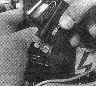
Photo 25.51V....and disconnect the electrical plug from the relay.
52. Install the relay in the reverse order.
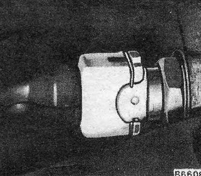
Fuel pressure control
53. The fuel pressure regulator is located between injectors 3 and 4 (see photo).
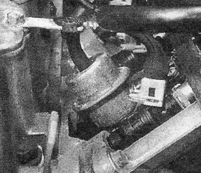
Photo 25.53. Pressure regulator.
54. Clamp the fuel hoses to prevent fuel leakage.
55. Disconnect the fuel hoses and vacuum hose from the pressure regulator.
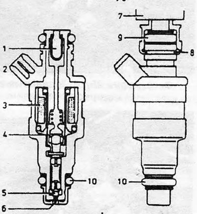
Pic. 3.55. Fuel burner (sectional view):1. Strainer; 2. Electrical connector; 3. Solenoid coil; 4. Solenoid plunger; 5. Injector nozzle needle; 6. Distribution axis; 7. Connecting the line from the fuel distributor; 8. Fuse holder; 9. Upper O-ring; 10. Bottom O-ring.
56. Install the regulator in the reverse order.
Pic. 3.56. Air Flow Sensor Removal - LE Jetronic System
Pic. 3.57. Coolant temperature sensor
Visitor comments