
Fast idle
1. The engine must be at normal operating temperature and the idle speed and mixture must be properly adjusted. To make work easier, remove the air cleaner.
2. Install the fast idle screw to the second highest shoulder of the fast idle cam. Connect a tachometer to the engine. Check that the air damper is completely open.
3. Start the engine without pressing the gas pedal and compare the engine speed with the value specified in the Specifications. If adjustment is necessary, break the plug covering the fast idle speed adjustment screw and adjust the speed using it (see photo).
Photo 16.3. Fast idle adjustment screw (shown by arrow) — The carburetor has been removed for clarity reasons.
4. Having achieved the desired speed, turn off the engine and disconnect the tachometer.
Lowering mechanism (discoveries) air damper
5. Remove the air cleaner.
6. Remove 3 screws, remove the retaining ring and then the suction cover. There is no need to disconnect the cooling system hoses, just move the cover to the side. Notice how the end of the bimetallic spring is attached to the choke actuator arm (see photo).
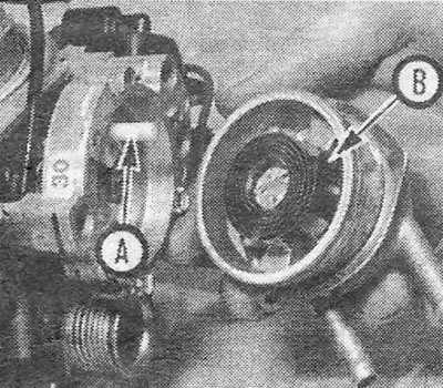
Photo 16.6. A loop (IN) at the end of the bimetallic spring must be engaged with the drive lever (A) air damper.
7. Move the choke control lever until it is completely closed. Install the fast idle screw at the highest cam shoulder.
8. Apply vacuum to the lowering block (discoveries) air damper (to the hose closest to the carburetor body). Lightly press the choke control lever in a clockwise direction (how to close the damper) and measure the gap between the edge of the valve and the wall of the neck by inserting a drill of a suitable size between them (see photo).
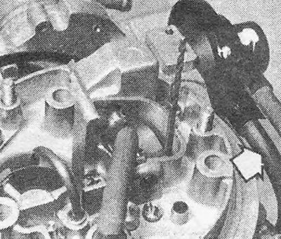
Photo 16.8. Checking the clearance when lowering the air damper using a drill. Apply vacuum to the hose shown by the arrow.
9. If adjustment is necessary, turn the adjusting screw located on the side of the suction housing (see photo).
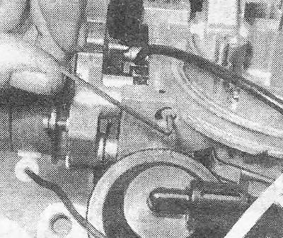
Photo 16.9. Screw for adjusting the gap of the lowered air damper.
10. Reinstall the choke cover, making sure that the end of the spring is engaged in the choke actuator lever. When tightening the screws, align the marks on the choke cover with the marks on its body (see photo).
Photo 16.10. Installation marks on the cover and suction housing (shown by arrows).
Vacuum units - checking for loss of tightness
11. If you have a vacuum source with a vacuum gauge, apply approximately 300 mbar of vacuum to the lowering block (discoveries) air damper (to the hose closest to the carburetor body). Shut off the vacuum source and check whether the block maintains a vacuum. If the block is leaking, find and repair or replace the leaking part.
12. Check the vacuum block of the secondary throttle valve in the same way.
13. If you do not have a vacuum source, the tightness of the vacuum blocks can be checked by test replacing them.
Visitor comments