
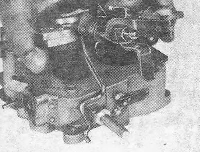
Carburetor with automatic choke
1. The carburetor very rarely requires a complete overhaul, but if such a need does arise, it seems more economical to simply replace the carburetor with a new one.
2. As a rule, the first few operations described in the following paragraphs are sufficient to allow the jets and float chamber to be cleaned.
3. Remove the carburetor, clean the outside of it from dirt and disconnect the vacuum hose from the vacuum suction unit.
4. Remove 3 screws from the automatic suction ring and remove the suction unit.
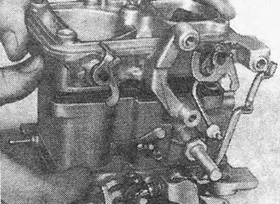
5. Pull out the cotter pin and disconnect the accelerator pump rod from the lever (see fig. 3.24).
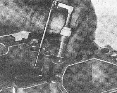
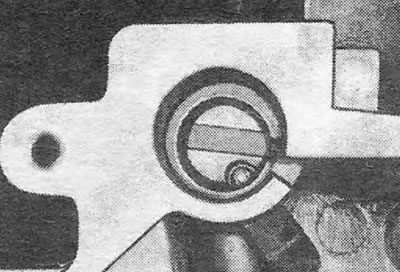
6. Unscrew the fuel inlet fitting and pull out the strainer from it (see photo).
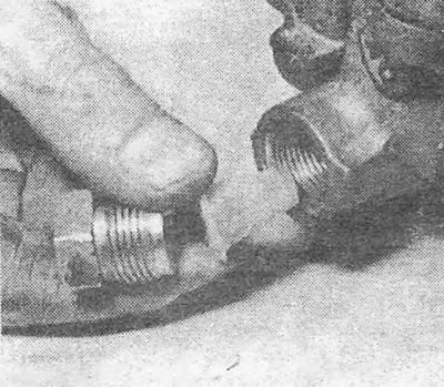
Photo 13.6. Fuel inlet fitting with strainer.
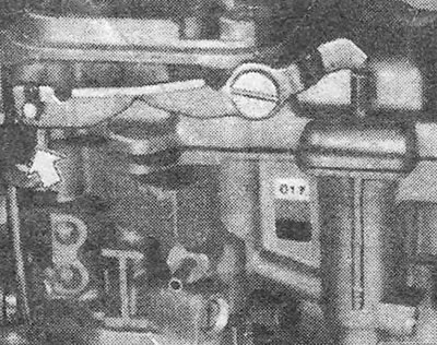
7. Remove the retaining ring and disconnect the choke connecting rod from the cam (see fig. 3.25).
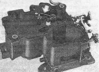
8. Remove 3 short and 4 long bolts securing the carburetor cover (see photo).
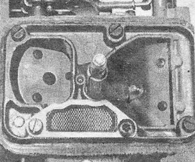
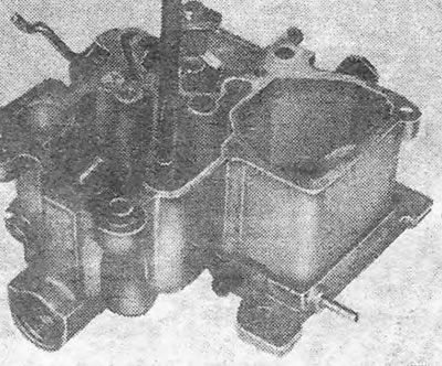
Photo 13.8. Varajet carburetor top cover.
9. Remove the cover, ensuring that the gasket remains in place on the float chamber flange. Remember that the accelerator pump plunger is under spring pressure.
10. Remove the plunger and spring of the accelerator pump and carefully tear off the carburetor cover gasket (see photo). Remove the pump suction valve spring retainer (see fig. 3.27).
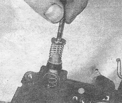
Photo 13.10. Removing the accelerator pump plunger and spring.
11. Remove the spring and needle of the vacuum piston of the first stage of the carburetor. Be careful not to bend the support bracket or the partial load system needle (see fig. 3.28 and 3.29).
12. If necessary, you can remove the partial load system plunger by grasping its stem with pliers.
13. Remove the sealing part, float and needle from the float chamber and drain the fuel from the chamber (see photo).
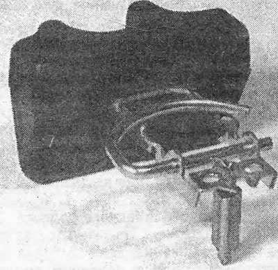
Photo 13.13. Removed float and fuel inlet valve.
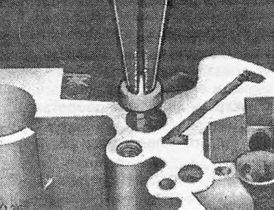
14. Note the location of the jets and remove them (see fig. 3.31 and 3.32).
15. Unscrew the 4 mounting screws and remove the throttle valve assembly (see Fig.3.33).
16. Further disassembly of the carburetor is not recommended.
17. Clean all parts and replace worn or damaged ones. If the throttle valve is worn, the entire throttle valve assembly must be replaced. Blow out the jets and their channels with compressed air (Do not under any circumstances try to clean them with wire, as... you will ruin the calibration of the jets).
18. Obtain a carburetor repair kit containing all the necessary parts, including gaskets.
19. Reassemble the carburetor in the reverse order. Please note the following points.
20. When assembling the accelerator pump, check that the check ball is installed correctly (see fig. 3.35).
21. Check that the needle valve spring is installed correctly (see fig. 3.36).
22. When replacing the carburetor cover, be careful not to jam the accelerator pump plunger.
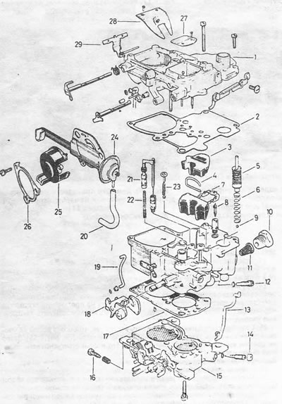
Pic. 3.22. GM Varajet carburetor: 1. Cover; 2. Gasket; 3. Sealing part; 4. Float pin; 5. Acceleration pump plunger; 6. Spring; 7.Float; 8. Fuel inlet needle valve; 9. Locking ball; 10. Receiving fuel fitting; 11. Fuel filter; 12. Bypass screw; 13. Connecting rod; 14. Quality screw; 15. Throttle valve assembly; 16. Fast idle screw with spring; 17. Gasket; 18. Fast idle cam; 19. Connecting rod of the fast idle system; 20. Vacuum hose; 21. Part load system needle valve and piston; 22. Spring; 23. Suction valve and shut-off ball; 24. Carburetor vacuum block; 25. Choke housing cover; 26. Cover lock; 27. Air damper (primary chamber); 28. Reflective flap (secondary camera); 29. Full load system needle valve.
23. Check that the breather mesh is in place.
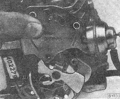
Pic. 3.23. Support bracket for automatic choke unit - GM Varajet carburetor
24. Check that the metal spring of the automatic choke is connected to the choke axle lever (see fig. 3.37).
Pic. 3.24. Connecting the rod to the accelerator pump lever (shown by arrow) - GM Varajet carburetor
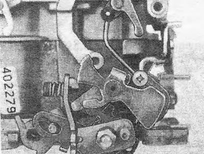
25. Check the operation of the throttle lever. Remember that the secondary damper will not open until the primary is 2/3 of its travel open. The secondary throttle valve will not open until the choke valve is fully open after the engine has reached operating temperature.
Pic. 3.25. Connection of choke rod to cam - GM Varajet carburetor
26. Make those checks and adjustments (see section 11), which can only be performed on a removed carburetor.
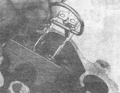
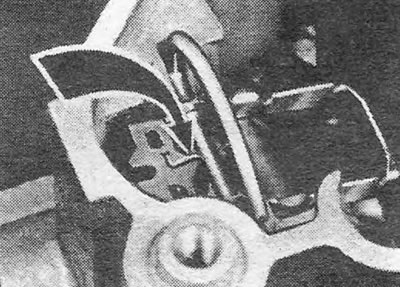
Pic. 3.26. Removing the GM Varajet Carburetor Cap
27. After installing the carburetor on the engine, adjust the idle speed and mixture composition (CO content in the exhaust) (see section 10). Carry out other checks and adjustments (see section 11).
Pic. 3.27. Removing the pump suction valve spring retainer - GM Varajet carburetor
Carburetor with manual choke
28. The operations are similar to those described above for a carburetor with automatic choke. Only exclude references to automatic suction parts.
Pic. 3.28. Removing the vacuum piston, spring and needle (shown by arrow) — GM carburetor
Pic. 3.29. Part Load System Needle Removal - GM Varajet Carburetor
Pic. 3.30. Removing the sealing part and float - GM Varajet carburetor
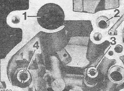
Pic. 3.31. Location of jets and holes on the carburetor - GM Varajet carburetor: 1. Acceleration pump cylinder 2. Vacuum valve spring hole; 3. Main jet; 4. Fuel inlet valve seat.
Pic. 3.32. Removing the jet from a GM Varajet carburetor
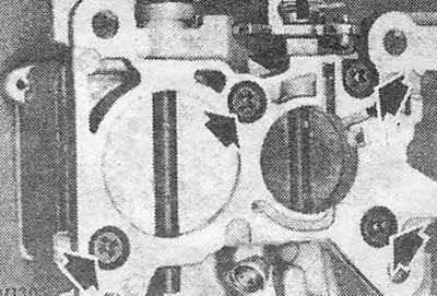
Pic. 3.33. Throttle Assembly Screws (shown by arrows) - GM Varajet carburetor
Pic. 3.34. Removing the Throttle Assembly - GM Varajet Carburetor
Pic. 3.35. Accelerator Pump Check Ball Location - GM Varajet Carburetor
Pic. 3.36. Fuel inlet valve with spring (shown by arrow) - GM Varajet carburetor
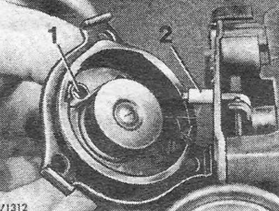
Pic. 3.37. Automatic choke body - GM Varajet carburetor: 1. Bimetallic spring; 2. Air damper axis lever.
Visitor comments