


2. Remove the hoses and wires from the carburetor, making marks to avoid confusion during assembly.
3. Access to the jets and float chamber can be gained by removing the top half of the carburetor, which is attached with five screws. Blow out the jets and holes with compressed air, never with a wire. If jets need to be removed, unscrew them carefully with a well-suited tool.
4. Remove the fuel strainer from the inlet manifold.
5. Clean the float chamber. Replace the inlet needle valve if it is worn or has had a high mileage. Replace the float if it is leaky or otherwise damaged.
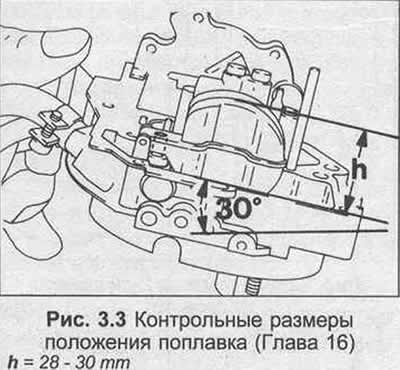
6. It is not possible to adjust the float's upper setting, as it depends on the float's weight, which is between 5.75-5.95 grams. However, it is possible to check the initial setting as follows. Turn the carburetor cover over, measure the distance from the joint surface to the farthest edge of the float (Figure 3.3). The ball of the tension spring in the needle valve should not be pressed during the inspection. The distance should correspond to the data in the Specifications.

7. Replace the diaphragms in the load enrichment valve and in the accelerator pump. Replace the fuel inlet strainer. Prepare a gasket kit.
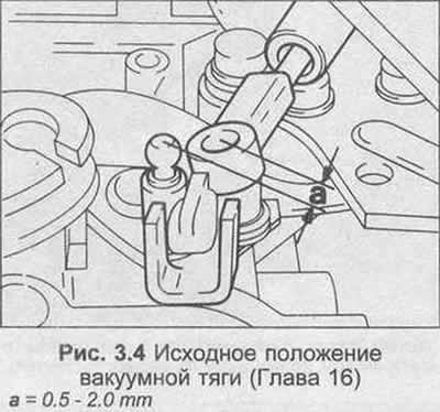
8. To remove the 2nd vacuum chamber, remove the rod from the ball end of the lever and unscrew the suspension screws. When installing the unit, the position of the rest of the rod should be between 0.5-2.0 mm from the ball end of the lever, as shown in Figure 3.4. This ensures pre-tensioning of the rod when connecting.
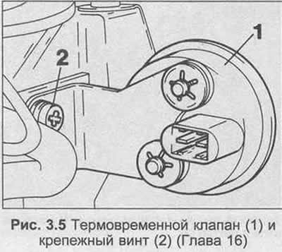
9. The thermal time valve can be removed by unscrewing the suspension screw (Figure 3.5).
10. Carburetor assembly is carried out in the reverse order of dismantling, use new gaskets and seals. Lubricate the rods with a small amount of oil.
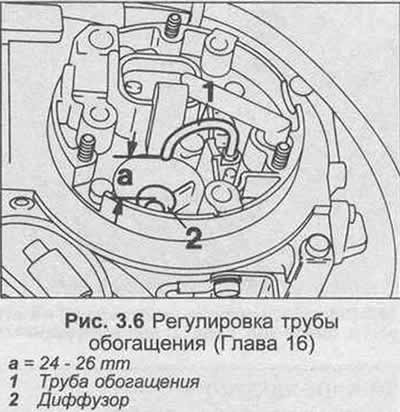
11. See Figure 3.6 and check that the distance between the enrichment pipe and the diffuser is 24-26 mm. Also check that the pipe is vertical above the center of the diffuser.
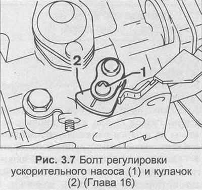
12. The operation of the accelerator pump can be checked as follows: (the fuel in the float chamber must be maintained at the correct level). On models with automatic transmission, first adjust the damper upwards (Chapter 17). Rotate the automatic choke cam, releasing it from the fast idle adjustment screw. Place the carburetor over a suitable container, then open and close the throttle ten times for about one second, wait about three seconds and repeat again. Divide the amount of fuel collected by ten and compare with the data in the Specifications. If adjustment is necessary, see Figure 3.7, loosen the bolt and re-set the cam as required, noting that turning the cam clockwise increases the pump output, and turning it counterclockwise decreases the pump output.
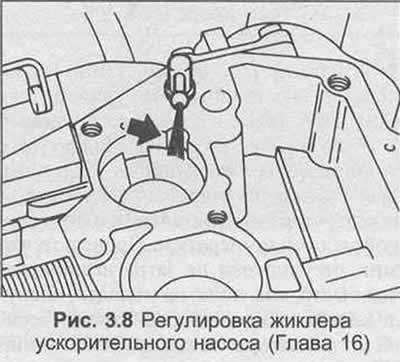
13. Check that the accelerator pump jet directs fuel to the recess as shown in Figure 3.8. If not, the carburetor cover must be removed to reposition the jet.
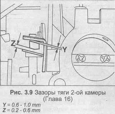
14. See Fig. 3.9 and check that the 2nd chamber linkage settings are as shown, with the 1st chamber throttle valve in the idle position. If necessary, bend the fork to correct the setting.
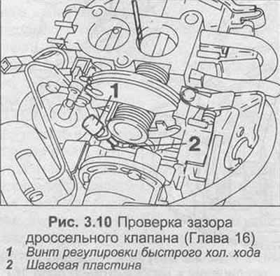
15. Turn the carburetor over, set the fast idle adjustment screw to the highest cam position. Using a twist drill, check the clearance between the primary throttle valve and the bushing, compare with the data in the Specifications for throttle valve clearance. This provides an initial setting for a higher idle speed. Adjust the fast idle adjustment screw if necessary.
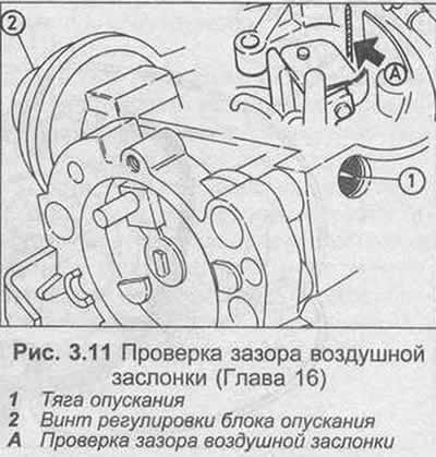
16. To check the choke clearance, first check that the descending diaphragm does not leak, then disconnect the vacuum pipe from the diaphragm. Close the choke completely, place the adjusting screw in the highest position of the fast idle cam. Using a small screwdriver, push the diaphragm rod to the first pressure point. With the rod in this position, using a drill, check the "small" choke clearance between the choke and the hole (Fig. 3.11). If necessary, adjust it by turning the block adjusting screw. If the "small" choke clearance is correct, push the rod completely into the diaphragm, then repeat the measuring procedure and check the "large" choke clearance. Again, if necessary, adjust the clearance by turning the block adjusting screw.
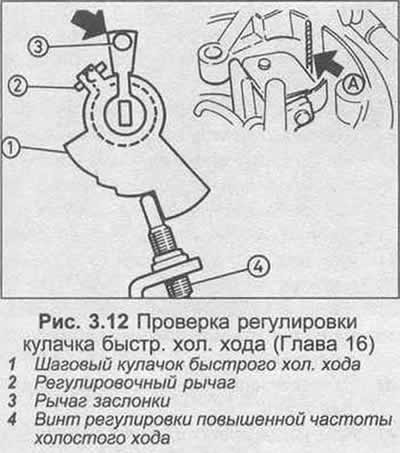
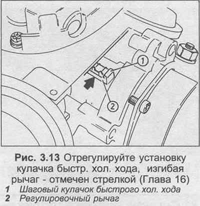
17. If only the choke clearance is adjusted correctly, check the adjustment of the high speed, idle cam as follows. Referring to Figure 3.12, open the throttle valve, lightly press the throttle lever in the direction of the arrow, then close the throttle valve again; the adjustment screw should now be set to the second step of the cam. Using a drill, check the clearance between the choke and the hole. If necessary, adjust the fast idle clearance by gently bending the lever (Fig. 3.13), being careful not to damage the return springs.
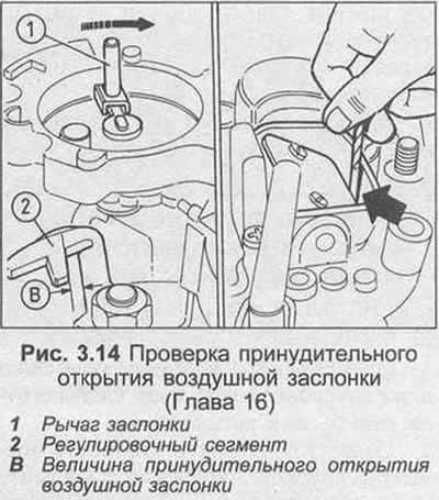
18. Next, check the positive choke opening as follows. Referring to Figure 3.14, rotate the choke lever in the direction of the arrow until it touches the stopper. Secure the lever in this position using a rubber band, then fully open the throttle valve and measure the positive choke opening (dimension "B"). If adjustment is necessary, carefully increase the clearance using a screwdriver or decrease it using a pair of pliers. After setting the clearance, remove the rubber band from the choke lever.
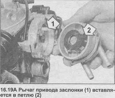
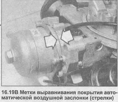
19. Install the throttle cover onto the carburetor by inserting the lever into the loop of the cover spring and aligning the marks (photo).
Visitor comments