
OpelBook.ru
Cars AvtoVAZ Cars Mitsubishi Cars BMW Cars Mercedes Cars Nissan Cars Toyota Cars Chevrolet
English Русский
Български
Беларускі
Український
Српски
Hrvatski
Română
Polski
Slovenský
Magyar
 |  Sitemap  |  Contacts  |    


Main Astra Corsa Insignia Kadett Omega Vectra Zafira Others Articles
Frontera A (1991-1998, petrol) Frontera B (1998-2004) Ascona C (1981-1988) Vivaro A (2001-2014)
  • Main
  • Opel
  • Ascona C
  • Power unit
  • Fuel and exhaust system
  • Fuel tank — removal and installation

Fuel tank — removal and installation (Opel Ascona C)

            0

Attention: work must be carried out in compliance with fire safety measures.


1. Disconnect the negative battery cable. Suck the fuel out of the tank into a clean metal container that can be sealed tightly. Alternatively, while working under the vehicle, disconnect the fuel line from the tank and drain the fuel into a suitable container.

2. Measure the length of the exposed thread of the short handbrake cable at the equalizing joint (for subsequent installation) and disconnect the cable.

3. Remove the exhaust system (see section 30) in order to provide space for removing the tank.

4. Disconnect the long handbrake cable from the rod.
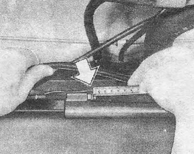
Figure 3.4. Measuring the exposed thread of the short handbrake cable (shown by arrow)

Figure 3.4. Measuring the exposed thread of the short handbrake cable (shown by arrow)


5. Bend the bracket under the tank up and back.
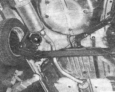
Figure 3.5. The exhaust pipe runs under the fuel tank, but above the rear axle beam

Figure 3.5. The exhaust pipe runs under the fuel tank, but above the rear axle beam


6. Disconnect from the tank and clamp the fuel outlet line (see photo). Please note that on injection models it is connected to the fuel gauge sensor (see photo 6.2).
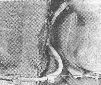
Photo 7.6. Fuel tank outlet hose (carburetor models).
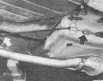
Photo 7.6. Fuel tank outlet hose (carburetor models).


Figure 3.6. Connecting the handbrake cable to the rod (shown by arrow)

Figure 3.6. Connecting the handbrake cable to the rod (shown by arrow)


7. Disconnect the wiring from the sensor terminals.
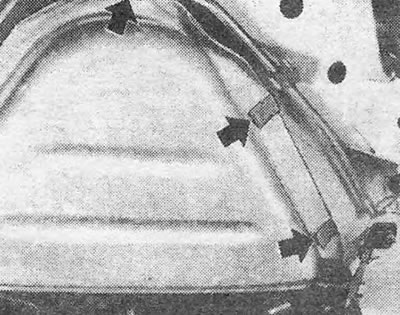
Figure 3.7. Rubber buffers on the left fuel tank mounting bracket (shown by arrows)

Figure 3.7. Rubber buffers on the left fuel tank mounting bracket (shown by arrows)


8. Release the clamps and disconnect the filler neck hose and short vent hose from the tank (see photos).
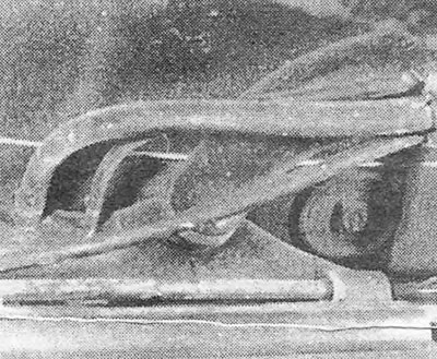
Photo 7.8A. Fuel filler hose and fuel tank vent hose connections.
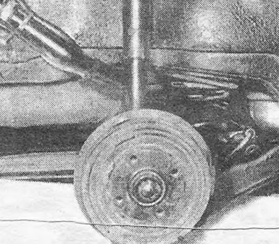
Photo 7.8A. Fuel filler hose and fuel tank vent hose connections.


Photo 7.8B. Location of the filler neck hose/vent hose under the rear fender.

Photo 7.8B. Location of the filler neck hose/vent hose under the rear fender.


9. Support the tank with a jack, placing a wooden block underneath it.

10. Loosen the tank mounting brackets (see photo) and lower the tank so that the long ventilation hose and fuel supply line can be disconnected from it (where are there).
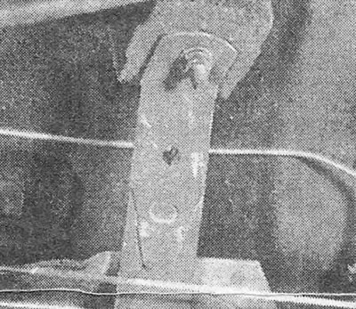
Photo 7.10. Fuel tank mounting bracket.

Photo 7.10. Fuel tank mounting bracket.


11. Remove the tank from the car.

12. If there is sediment or water at the bottom of the tank, you can clean it by rinsing it 2-3 times with kerosene and shaking it vigorously. Before flushing, remove the sensor from the tank (see section 6). Let the kerosene drain completely.

13. If the tank was removed to fix a leak, it should be taken to a specialist for repair. Do not attempt to weld or solder the tank yourself under any circumstances, as it contains explosive gasoline vapors.

14. The tank is installed in the reverse order. Please note the following points:
  • a. Replace the hose clamps with new ones
  • b. Check that the rubber buffers are in place on the left tank mounting bracket (see figure 3.7)
  • c. Check the adjustment of the hand cable (see chapter 9).


This article is available at russian, bulgarian, belarusian, ukrainian, serbian, croatian, romanian, polish, slovak, hungarian
Checking the article: Kornev Georgy

Share information:

Previous articles
Opel Ascona C: Fuel and exhaust system
Next articles

Fuel tank sensor — removal and installation
Fuel pump — description, maintenance, inspection, removal and installation
Air Cleaner — Maintenance, Removal and Installation
Air purifier — description and testing
Fuel and exhaust system — routine maintenance
General description
Fuel tank ventilation chamber — description, removal and installation
GM Varajet Carburetor — Description
GM Varajet Carburetor — Idle Speed and Mixture Control
GM Varajet Carburetor — Engine Adjustment
GM Varajet Carburetor — Removal and Installation
GM Varajet Carburetor — Overhaul


See similar ones from other Opel car manuals:
▶ Fuel tank — removal and installation Opel Astra F (1991-1998, petrol)
▶ Fuel tank Opel Corsa C (2000-2006, petrol)
▶ Removal fuel from the tank Opel Insignia A (2008-2017)
▶ Fuel tank — removal and installation Opel Omega A (1986-1993)
▶ Fuel tank — removal, inspection and installation Opel Vectra A (1988-1995, petrol)
Link to this page in different formats

Visitor comments


No comments yet


How much will 13 + 34 =


Vivaro A (2001-2014) 
  • General information
  • User manual
  • Power unit
  • Petrol engine F4R
  • Diesel engine F9Q
  • Diesel engine G9U
  • Transmission
  • Clutch and drive shafts
  • Manual gearbox
  • Chassis
  • Front suspension
  • Rear suspension
  • Brake system
  • Body
  • Exterior
  • Interior
  • Electrical equipment
  • Heating and ventilation
  • Air conditioner
  • Equipment and devices
  • Electrical diagrams
Ascona C (1981-1988) 
  • General information
  • Maintenance
  • Power unit
  • Gasoline engines
  • Diesel engines
  • Cooling system
  • Fuel and exhaust system
  • Contact ignition system
  • Contactless ignition system
  • Transmission
  • Clutch
  • Mechanical gearbox
  • Automatic gearbox
  • Drive shafts
  • Chassis
  • Steering
  • Brake system
  • Car suspension
  • Body
  • Exterior
  • Interior
  • Doors and windows
  • Electrical equipment
  • Equipment and devices
  • Power devices
  • Electrical circuits
Frontera B (1998-2004) 
  • General information
  • User manual
  • Maintenance
  • Power unit
  • Petrol engines 2.2 l
  • Petrol engines 3.2 l
  • Diesel engines 2.2 l
  • Cooling system
  • Fuel system (petrol)
  • Fuel system (diesel)
  • Ignition system
  • Transmission
  • Clutch
  • Manual gearbox MUA5C
  • Automatic gearbox 4L30E
  • Chassis
  • Suspension and axles
  • Steering
  • Brake system
  • Body
  • Exterior
  • Interior
  • Doors, locks and windows
  • Heating and air conditioning
  • Electrical equipment
  • Power devices
  • Equipment and devices
  • Lighting and signaling
  • Electrical diagrams
Frontera A (1991-1998, petrol) 
  • General information
  • Introduction to guide
  • User manual
  • Maintenance
  • Power unit
  • Engine repair
  • Lubrication system
  • Cooling system
  • Power and exhaust system
  • Engine electrics
  • Transmission
  • Clutch
  • Mechanical gearbox
  • Cardan shafts
  • Chassis
  • Brake system
  • Front suspension
  • Rear suspension
  • Steering
  • Body
  • Repair and care
  • Electrical equipment
  • Equipment and devices
  • Electrical circuits
OpelBook.ru © 2017–2026 · Mobile version · · Sitemap: EN BG BY UA RS HR RO PL SK HU · Feedback · Site search
Astra F, petrol · Astra G, petrol · Astra G · Astra H · Astra J, petrol · Corsa B · Corsa C, petrol · Corsa C · Insignia A · Kadett D · Kadett E · Omega A · Omega B · Omega B2 · Vectra A, petrol · Vectra A · Vectra B, petrol · Vectra B · Vectra C · Zafira A, petrol · Frontera A, petrol · Frontera B · Ascona C · Vivaro A ·
We want your visit to be comfortable 🤝! We use cookies 🍪 to make that happen.