


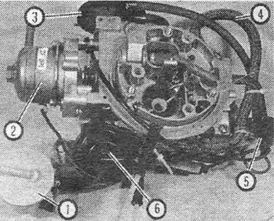
Photo 14.1A. Pierburg carburetor - top view:1. Steam separator; 2. Choke cover; 3. Air damper lowering (opening) block; 4. Fuel hose; 5. Vacuum switch; 6. Secondary throttle valve vacuum block.
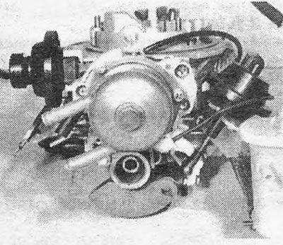
Photo 14.1B. Pierburg carburetor - view from the choke cover side.
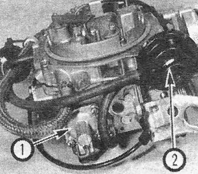
Photo 14.1C. Pierburg carburetor - view from the side of the accelerator pump (1) and the air damper lowering (opening) unit (2).
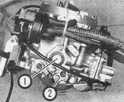
Photo 14.1D. Pierburg carburetor - view from the side of the mixture enrichment valve at partial loads (1) and the accelerator pump cam (2).
2. The automatic choke is of the conventional type and is controlled by a bimetallic spring. The choke cover is heated by electric current and coolant, which ensures a quick response to changes in engine and outside air temperature. Excessive suction is eliminated by the eccentric placement of the air damper, the vacuum damper lowering system and the connection of the air damper with the throttle mechanism.
[Article posted on a web portal: Opelbook.ru]
3. With the engine at normal operating temperature, the idle mixture is supplied through the bypass system. Although some illustrations show an idle cut-off valve, none of the carburetors we examined had such a valve, and idle speed was adjusted at the throttle stop screw.
4. The throttle valves open sequentially. The primary valve opens mechanically and the secondary valve opens due to the vacuum developing in both air passages, but the secondary throttle valve cannot open until the primary valve is at least half open. For reliability reasons, both throttle valves are closed mechanically.
5. Efficient engine operation at any speed and load is ensured by the partial load enrichment valve and the primary and secondary transition systems. The accelerator pump provides the extra fuel needed for rapid acceleration.
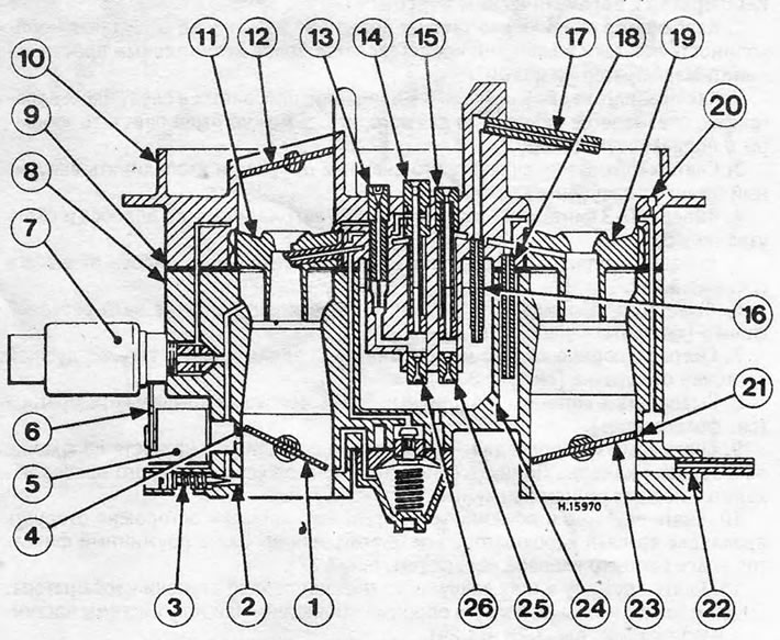
Figure 3.40. Pierburg carburetor: accelerator pump parts: 1.Primary throttle valve; 2. Primary pre-spray; 3. Cam; 4. Pump inlet valve; 5. Spring; 6. Membrane; 7. Pump lever; 8. Plunger; 9. Lid; 10. Return jet; 11. Exhaust valve; 12. Injector tube.
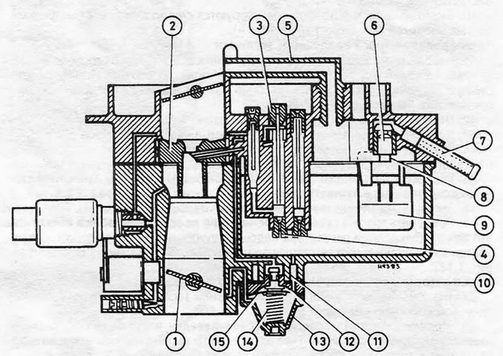
Figure 3.41. Pierburg carburetor: throttle actuator: 1. Primary throttle valve; 2. Secondary throttle valve; 3. Throttle stop screw; 4. Segment lever; 5. Throttle lever; 6. Fast idle speed adjusting screw; 7. Secondary locking lever; 8. Mounting bracket; 9. Vacuum block; 10. Spring; 11. Fork lever; 12. Secondary stop screw.
Visitor comments