
Air box - removal and installation
Disconnect the breather hose from the air box.
Disconnect the two vacuum tubes from the air box, noting their location.
Loosen the screw and disconnect the air lines from the end of the air box.
Remove the two screws and separate the air box from the fuel injection device. Remove the sealing ring.
Installation is carried out in the reverse order of removal, taking into account the following.
Check O-rings for damage or aging and replace if necessary. Check if the O-ring is correctly positioned in the groove of the airbox.
Connect the vacuum tubes in the same way as they were before removal.
Fuel injection device
Removing
Relieve pressure in the fuel system by removing the fuel pump relay, (chapter 12) and cranking the crankshaft with the starter for 5 seconds.
Disconnect the negative battery terminal.
Remove the air box from the top of the fuel injection device as previously noted.
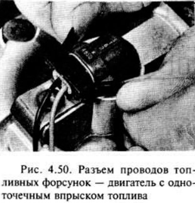
Remove the clamps and disconnect the wires from the fuel injectors.
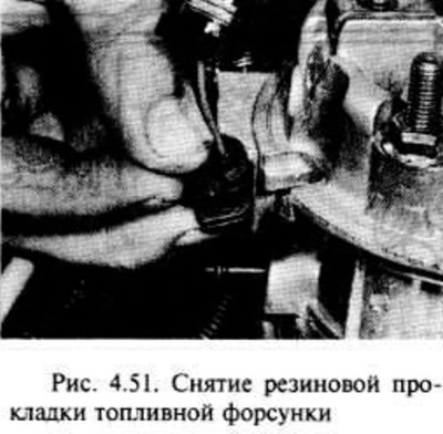
Remove the rubber gasket from the top of the fuel injection device, then remove the fuel injector gasket from the groove. Move the wire to one side.
Disconnect the wiring from the idle control motor and throttle position sensor.
Disconnect the fuel supply and return hoses, noting their location. The possibility of fuel leakage requires fire safety measures. Clamp hoses to reduce fuel loss.
Disconnect the vacuum hoses from the fuel injection device.
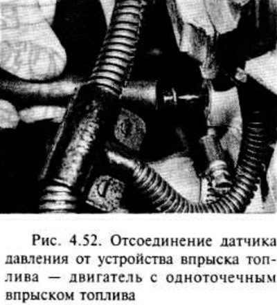
Disconnect the pressure sensor from the back of the fuel injection device.
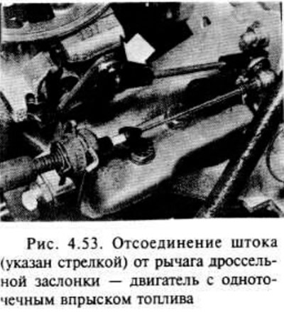
Disconnect the stem from the throttle lever.
Ensure that all relevant hoses and wires are disconnected and allow the fuel injection device to be removed.
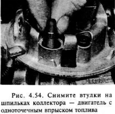
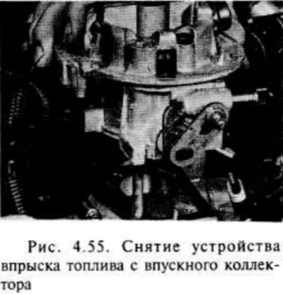
Unscrew the two nuts, remove the washers, remove the bushings that are on the manifold bolts, then carefully separate the fuel injection device from the intake manifold. Remove the gasket.
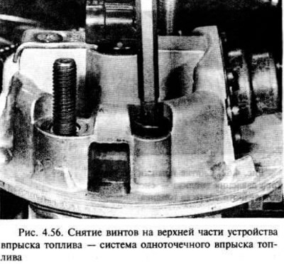
If desired, the fuel injection device can be separated into upper and lower sections by removing two fixing screws (see fig. 4.56). You can remove the vacuum flange and fuel hose fittings.
Installation
Installation is carried out in the reverse order of removal, taking into account the following.
If required, install a new gasket when assembling the two sections of the fuel injection device, as you did when installing the vacuum hose flange. If the fuel hose fittings were removed, check that the gaskets are in place.
Install the fuel injection unit to the manifold with a new gasket, checking that the bushings are in their positions on the manifold. Lubricate the nut threads with sealant before installation. Make sure there are washers under the nuts.
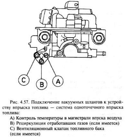
Check if all hoses are properly connected and spaced in the same way as before removal. Vacuum hoses should be connected like this. as shown in Figure 4.57.
Check and, if necessary, adjust the free play of the throttle cable.
Fuel burner
Removing
Relieve pressure in the fuel system by removing the fuel pump relay (chapter 12), while cranking the engine with the starter for about 5 seconds.
Disconnect the negative battery terminal.
Remove the air box from the top of the fuel injection device as directed in this section.
Squeeze the clamps and disconnect the fuel injector wires.
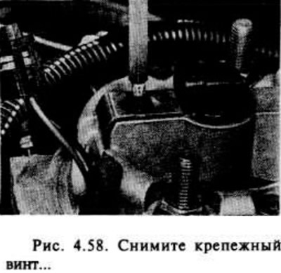
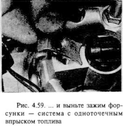
Remove the Tox countersunk screw and remove the nozzle clamp.
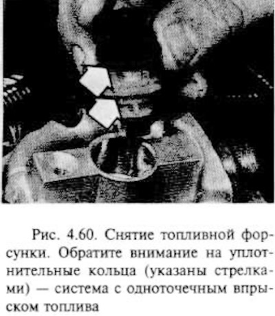
Carefully pull out the nozzle.
Installation
If the old nozzle is installed, replace the two o-rings at its base.
Carefully install the injector into the fuel injection unit so that the socket with the wire is directed towards the socket of the clamp screw.
Install the nozzle clamp, making sure it is properly connected to it (it should engage with the slots in the floor socket for the wire).
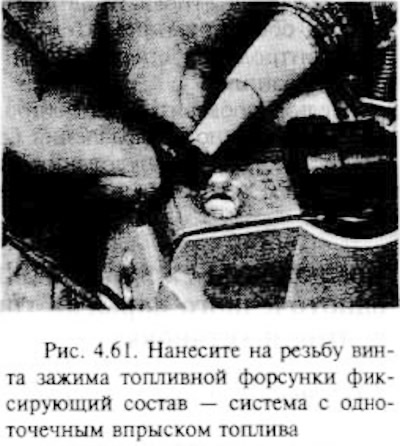
Apply locking compound to the clamp screw threads, then tighten the screw.
Connect the injector wiring and connect the negative battery terminal.
Fuel pressure control
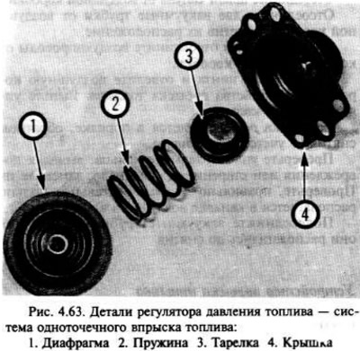
Note: The pressure regulator diaphragm must always be replaced when the regulator is removed. Use a suitable compound to secure the threads of the regulator cover mounting bolts.
Removal and installation
Relieve pressure in the fuel system by removing the fuel pump relay (see chapter 12) and cranking the crankshaft with the starter for about 5 seconds.
Remove the air box from the top side of the fuel injection device as previously noted.
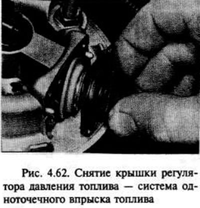
Remove the four Tox bolts on the fuel pressure regulator cover and carefully remove the cover.
Remove the poppet and spring and remove the diaphragm.
Installation is carried out in the reverse order of removal, taking into account that the diaphragm must be correctly placed in the recess of the fuel injection device, and apply the appropriate thread locking compound to the threads of the cover fastening bolts.
Throttle position sensor - removal and installation
Disconnect the negative battery terminal.
Remove the airbox from the top side of the fuel injection unit as above.
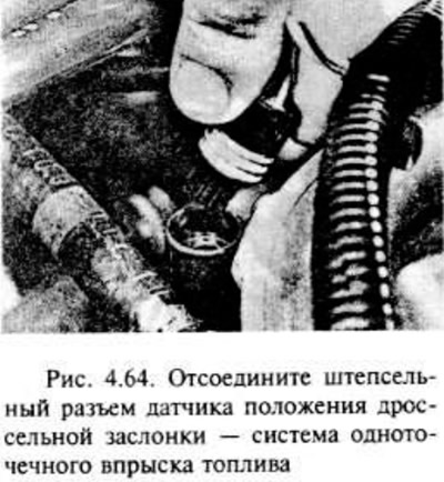
Disconnect the connector from the throttle position sensor.
Remove the two screws and remove the sensor from its socket in the fuel injection unit.
Check that the throttle is closed, then install the sensor in its socket, making sure that the sensor arm is properly engaged with the throttle shaft.
Coat the sensor bolts with thread locking compound and tighten them.
Installation is carried out in the reverse order of removal.
Idle control electric motor - removal and installation
Disconnect the negative battery terminal.
Remove the airbox from the top side of the fuel injection unit as above.
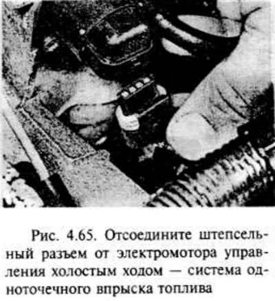
Remove the clip and disconnect the connector from the idle control motor.
Remove the two mounting screws and remove the electric motor from the side of the fuel injection unit. If required, remove the O-ring.
Installation is carried out in the reverse order of removal, taking into account the following.
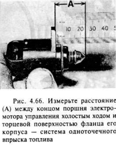
In order not to damage the housing during installation, it is necessary that the distance between the end of the motor piston and the end surface of the flange of the motor housing does not exceed 28.0 mm. Measure the indicated distance and, if the distance is greater than indicated, carefully push the piston into the motor housing.
Install the motor with a new O-ring so that the socket is facing down.
Apply an appropriate thread locking compound to the threads of the motor mounting bolts before installation.
Manifold pressure sensor - removal and installation
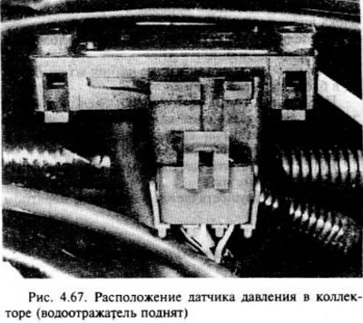
The sensor is located on the bulkhead of the engine compartment under the water deflector (fig 4.67).
Disconnect the negative battery terminal.
Raise the water deflector to access the sensor. Disconnect the sensor connector from the vacuum tube.
Pull the sensor up to release it from the bracket and remove it from the vehicle.
Installation is carried out in the reverse order of removal.
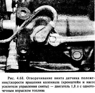
Crankshaft Position/Speed Sensor (engine 1.8 l)
Removing
The sensor is located on the side of the exhaust manifold on the engine, at the bottom of the cylinder block, behind the oil pump.
Disconnect the negative battery terminal.
If required, loosen the fastening clips of the appropriate outer distributor belt cover and disconnect the sensor wire from the distributor belt cover.
Disconnect the sensor connector, noting its location.
Turn away the screw and take out the gauge from the block of cylinders.
Installation
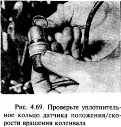
Check the sensor O-ring and. if necessary, replace it.
Installation is carried out in the reverse order of removal. In this case, it is necessary to ensure that the sensor wire is correctly located on the timing belt cover (where necessary), and that the plug is also correctly installed.
Refrigerant temperature sensor
The sensor is located behind the intake manifold on the right side.
Disconnect the negative battery terminal.
Partially drain the refrigerant from the cooling system.
Disconnect the sensor connector (see fig. 4.70).
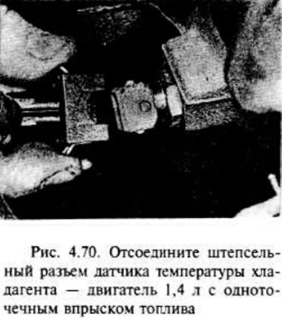
Loosen the sensor screws and remove it from the intake manifold. Remove the O-ring, eats and required.
Installation is carried out in the reverse order of removal, however, a new sealing ring must be used, and when finished, fill the cooling system.
Exhaust oxygen sensor
Disconnect the negative battery terminal, then disconnect the oxygen sensor connector, noting its location (pic. 4.71).
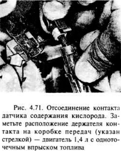
Using a suitable wrench, remove the sensor from the intake manifold (wear gloves when working with a hot exhaust system).
Remove the sensor and its wires, being careful not to burn the wiring when touching the exhaust system.
The sensor is installed when the engine and exhaust system are still at normal operating temperature.
If a new sensor is installed, the bolt threads are coated with a special grease to prevent "grasping" sensor in the exhaust pipe.
If the old sensor is installed, carefully wipe the threads. It should be coated with Vauxhall/Opel special grease. N 19 48 602. Use only special grease containing graphite and glass beads.
Installation is carried out in the reverse order of removal.
Visitor comments