
Throttle body
Removing
Disconnect the negative battery terminal.
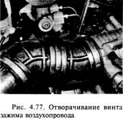
Loosen the screws securing the air duct to the throttle body and air cleaner cover, then remove the air duct.
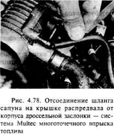
Disconnect the breather hoses on the camshaft cover from the throttle body.
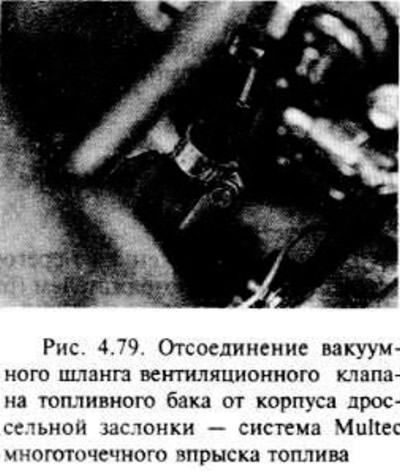
Disconnect the fuel tank vent valve vacuum hose from the throttle body.
Disconnect the manifold pressure sensor vacuum hose from the throttle body.
Disconnect the cooling hoses from the throttle body. Possible fluid leakage requires precautions, clamp hoses to prevent leakage.
Disconnect the connector from the throttle position sensor and from the idle control motor.
After loosening the clamp, remove the swivel end of the cable from the throttle lever.
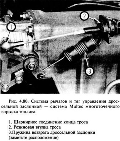
Remove the throttle cable bushing from the bracket located on the intake manifold, then unhook the throttle return spring hook from the bracket. If necessary, unhook the spring from the gasket in the throttle control system and lay the spring separately (in this case, it is necessary to note the location of the spring for its correct installation).
Check and make sure all hoses and wires are disconnected to allow removal of the throttle body.
Remove the four nuts and remove the throttle body from the intake manifold.
Remove the gasket.
If desired, the throttle position sensor and idle control motor can be removed from the throttle body as shown below.
Installation
Installation is carried out in the reverse order of removal, taking into account the following.
Where required, install the throttle position sensor and/or idle control motor as shown below.
Thoroughly wipe the mating surfaces of the throttle body and intake manifold and install a new gasket.
Check if all hoses and wires are properly installed.
Check the level and if necessary, add refrigerant.
After completing the work, check and, if necessary, adjust the free play of the throttle cable.
Fuel injectors
Removing
Disconnect the negative battery terminal.
Place a rag under the fuel line fitting at the fuel pressure regulator and reduce the pressure in the fuel system by slowly unscrewing the fuel line fitting. You will need two wrenches so that one of them can support the regulator while unscrewing the fitting. Fuel leaks are possible, so take fire prevention measures. Tighten the fitting after depressurizing.
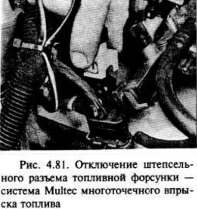
Disconnect the plug connector from the fuel injectors, take the wires to the side.
Disconnect the vacuum tube from the fuel pressure regulator.
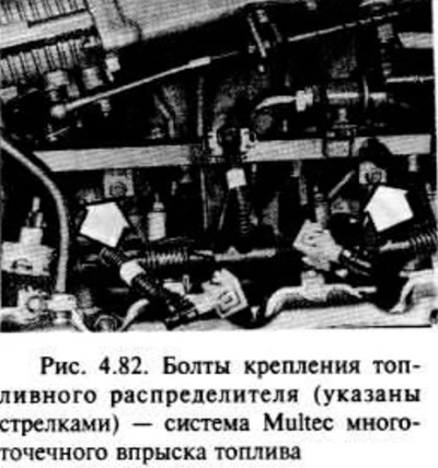
Unscrew the two bolts securing the fuel distributor, then lift it together with the injectors so that the injectors can be removed. Try not to stretch the fuel hoses. Possible fuel leakage, take fire precautions.
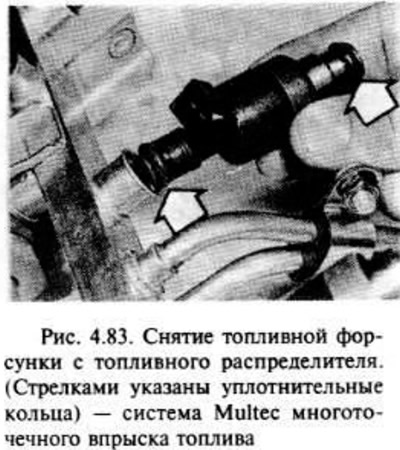
To remove the injectors from the fuel distributor, remove the metal clip with a screwdriver or pliers, then remove the injector.
Fuel injectors cannot be repaired, there are no spare parts for them. If they are defective, they must be replaced with new ones.
If desired, you can remove the fuel distributor assembly after disconnecting the two hoses. The hoses are most easily accessed from under the vehicle. Note the position of the hoses before disconnecting so that they can be reinstalled correctly later on.
Installation
Begin installation by replacing the gaskets with new ones on both ends of the fuel injector.
Installation is carried out in the reverse order of removal, however, check that all tubes and wires are connected correctly.
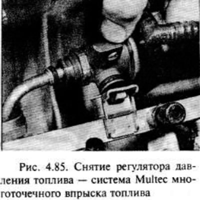
Fuel pressure regulator - removal and installation
Disconnect the negative battery terminal.
Disconnect the vacuum hose from the pressure regulator.
Place a rag under the fuel line fitting on the pressure regulator, then reduce the pressure in the fuel system by slowly unscrewing the fitting. Possible fuel leakage, take fire precautions. You will need two wrenches to hold the regulator with one of them. Disconnect the fuel line from the regulator after the pressure has been reduced. Plug the pipe to prevent fuel leakage.
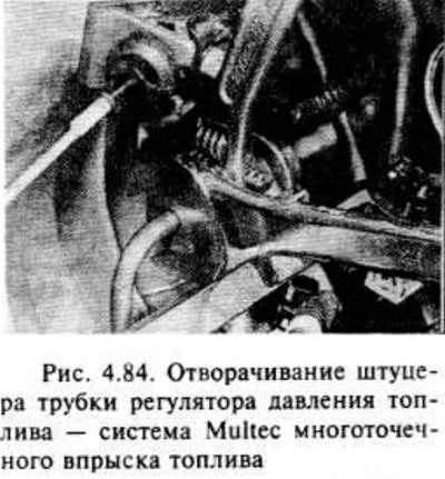
Turn away a bolt and take out a regulator of pressure from the fuel pipeline and the distributor of fuel.
Installation is carried out in the reverse order of removal, however, new o-rings must be used when connecting the regulator to the fuel line and distributor.
Throttle position sensor - removal and installation
Disconnect the negative battery terminal.
Press the clips and disconnect the plug connector from the damper position sensor.
Loosen the three screws and remove the sensor from the throttle body.
Installation is in the reverse order of removal, however, make sure that the sensor sliding contact is properly engaged with the throttle shaft and that the sensor is properly seated.
Idling simplification electric motor - removal and installation
Disconnect the negative battery terminal.
Release the clip and disconnect the connector from the idle control motor (see fig. 4.86).
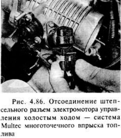
Loosen the two screws and remove the electric motor. If required, remove the O-ring.
Before installing the electric motor, check the condition of the sealing ring and, if necessary, replace it.
Installation is in the reverse order of removal, but make sure that the O-ring is installed correctly and that the motor plug is facing down.
Manifold pressure sensor
The procedure for performing work is as indicated in the previous section for engines with single point fuel injection
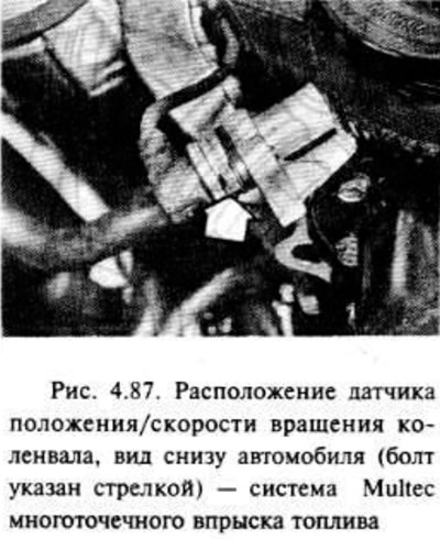
Crankshaft position / speed sensor - removal and installation
The sensor is located on the bracket of the lower part of the cylinder block, on the side of the engine intake manifold, next to the crankshaft pulley.
Disconnect the negative battery terminal.
Disconnect the sensor connector on the bracket located on the camshaft cover.
The easiest access to the sensor is possible from under the car. If desired, you can raise the car and secure its position with racks under the bridge.
Remove the screw and separate the sensor from the bracket. Note the location of the wiring to make installation easier.
Check the condition of the sealing ring and, if necessary, replace it.
Installation is carried out in the reverse order of removal. Check if the wiring and connections are correctly positioned.
After finishing work, check the gap between the working surface of the sensor and the gear sensor on the crankshaft pulley using a set of feelers. The gap must be as specified in the specification. If the gap is not maintained, the bracket must be replaced, since adjustment is not possible in this case.
Refrigerant temperature sensor
The procedure for performing the work is the same as indicated in the previous section for engines with single point fuel injection. Keep in mind that the sensor is located on the left side of the end surface of the cylinder head, under the distributor (or coil) ignition.
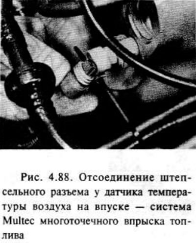
Inlet air temperature sensor in the air intake - removal and installation
The sensor is located on the left side of the intake manifold reservoir.
Disconnect the negative battery terminal.
Disconnect the sensor connector. Remove the sensor from the intake manifold. Installation is carried out in the reverse order of removal.
Exhaust oxygen sensor
The procedure for performing the work is the same as indicated in the previous section for engines with single point fuel injection.
Electronic control unit
The procedure for performing the work is the same as indicated in the previous section for engines with single point fuel injection. Please note that the control unit and program memory can be replaced separately.
Details of the evaporative emission system
See the relevant section in part "WITH" of this chapter.
Visitor comments