
Note: Before you start, see Chapter 2. Use new O-rings when installing the injector. You will need a tachometer and an exhaust gas analyzer to check the idle mixture.
Single overhead cam models
Removing
1. Disconnect the negative cable from the battery.
2. Turn off a nut, disconnect a vacuum hose of the amplifier of a brake from an inlet collector.
3. Remove the idle speed control along with hoses, if necessary, follow Chapter 22.
4. Disconnect the vacuum pipe from the fuel pressure regulator.
5. Disconnect the wiring harness cover from the fuel injectors, move it to the side; be careful not to deform the wiring. Pull the shroud, compress the wiring connector retaining clips to release the shroud from the injectors.
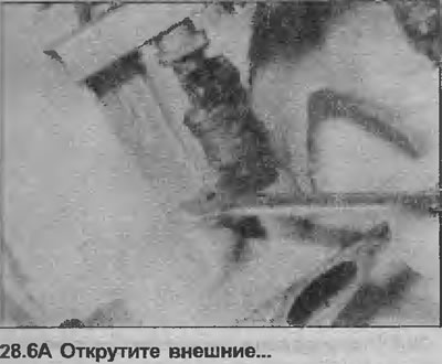
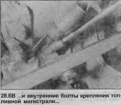
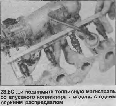
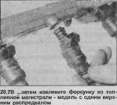
6. Unscrew the four bolts from the brackets securing the fuel line to the intake manifold, then lift the fuel line together with the injectors so that the injectors can be removed (see illustrations). Be careful not to deform the fuel supply hoses.
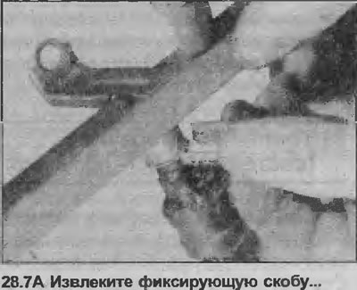
7. To remove the injector from the fuel line, remove the metal retaining clip with a screwdriver, then remove the injector from the fuel line (see illustrations).
Installation
8. Fuel injectors cannot be repaired because parts are not available. In case of malfunction, replace the nozzle.
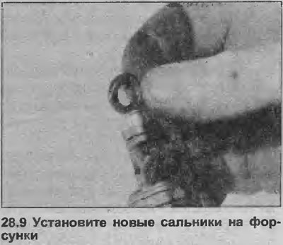
9. Begin installation by placing new seals on both ends of the injector (see illustration). Even if only one injector was removed, install new seals on all four.
10. Install in reverse order, making sure all hoses, pipes and wires are properly connected.
11. Finally, where available, check and adjust the idle mixture as described in Chapter 20.
Models with double overhead camshafts
Removing
12. Disconnect the negative cable from the battery.
13. Loosen the screw securing the main air line to the left end of the air flow meter.
14. Using a socket wrench, remove the four bolts securing the heater block to the throttle body. Lift the block off the throttle body, disconnect the hose from the base of the heater block, then remove the block.
15. Place a cloth under the fuel supply hose connector on the fuel line.
16. Slowly loosen the fuel supply hose coupling to relieve pressure in the fuel line, then disconnect the hose from the fuel line. Cap the end of the hose to prevent dirt from entering and further fuel leakage.
17. Repeat the steps described in paragraphs 15 and 16 with the remaining coupling connecting the fuel supply hose to the fuel line.
18. Disconnect the two breather hoses from the camshaft cover. Disconnect the larger rod from the throttle body and remove it.
19. Disconnect the vacuum pipe from the top of the fuel pressure regulator.
20. Disconnect the electrical wiring from the airflow meter. Remove the O-ring.
21. Disconnect the electrical wiring from the throttle position sensor.
22. Pull the end of the throttle cable away from the throttle lever on the throttle body, then unscrew the cable bracket from the intake manifold and move it to the side (see illustration).

23. Disconnect the wiring harness cover from the fuel injectors, move it to the side; be careful not to deform the wiring. Pull the wiring harness cover, squeeze the wiring connector retaining clips to release the cover from the injectors.
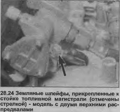
24. Turn off and remove two fixing nuts of a fuel line, remove a fuel line together with fuel atomizers from an inlet manifold. Note the position of the ground loops on the fuel line mount (see illustration).
25. To remove the injector from the fuel line, remove the metal retaining clip with a screwdriver, then remove the injector from the fuel line.
Installation
26. Installation is carried out as described in paragraphs 8-11 inclusive.
Visitor comments