
Note: In the event of damage, the major components of the fuel injection system should be diagnosed by a GM dealer or other person who has the necessary test equipment. If a defective component is identified, it can be replaced following the instructions given in this Chapter.
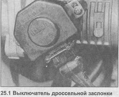
Throttle switch
1. Disconnect the wire from the switch (photo).
2. Turn off two fixing screws, disconnect the switch from a throttle axis.
3. Installation is carried out in reverse order, adjust the switch as described in Chapter 24.
Fuel injectors
4. Disconnect the negative battery cable.
5. Disconnect wires from injectors.
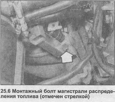
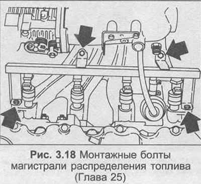
6. Remove the four bolts securing the fuel distribution line to the intake manifold (photo).
7. Use a screwdriver to remove the brackets that secure the injectors to the distributor line.
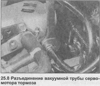
8. Unscrew the union nut, disconnect the brake servomotor vacuum pipe from the intake manifold (photo).
9. Remove the fuel feed pipe hanger.
10. Loosen the injectors on the distributor line and remove them from the intake manifold.
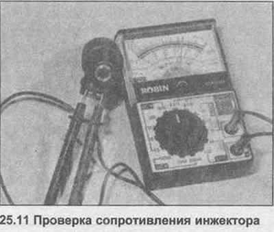
11. Connect an ohmmeter to the injector terminals, the resistance should be 16.0±1.0 ohm (photo).
12. Installation is carried out in the reverse order; if necessary, replace the injector O-rings.
Air flow sensor and control unit
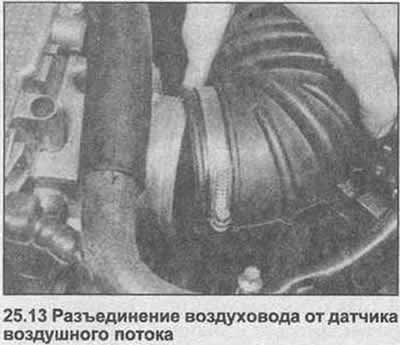
13. Loosen the bracket, disconnect the air duct from the air flow sensor (photo). Disconnect the multi-pin electrical wiring plug.
14. Release the spring clips, lift the airflow sensor and cover off the air filter housing.
15. Wipe the sensor air valve and check that it moves freely.
16. The control unit is located inside the sensor cover, which can be removed by unscrewing the four screws.
17. Installation is carried out in the reverse order.
Temperature sensor
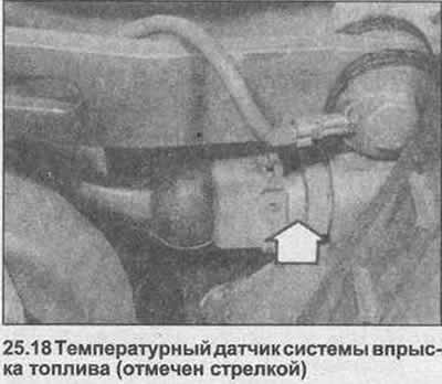
18. The temperature sensor is located near the generator on the side of the unit (photo).
19. Drain the liquid from the cooling system (Section 2).
20. Disconnect the wires and unscrew the sensor.
21. To test the sensor, connect an ohmmeter to the two clamps and compare the resistance with the data in the Specifications.
22. Installation is carried out in the reverse order. Fill the cooling system as described in Section 2.
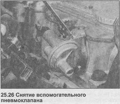
Auxiliary pneumatic valve
23. The auxiliary air valve is bolted to the side of the camshaft housing.
24. Disconnect the wires from the valve.
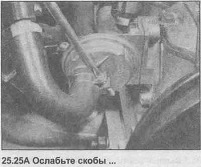
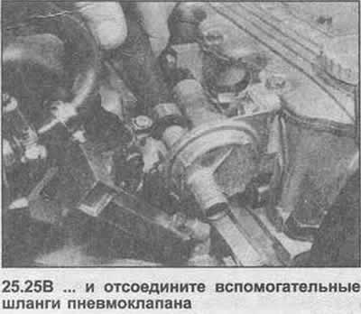
25. Loosen the hose clamps, disconnect the air hoses (photo).
26. Unscrew and remove the valve (photo).
27. The valve can be checked by looking through the hose connecting rod. The cold valve should be slightly open. When the valve is heated (apply 12 volts to the clamps) the regulator disc should move and block the hole.
28. Installation is carried out in the reverse order.
29. The control relay is located in the left rear corner of the engine compartment. Disabling the relay disables the fuel pump.
30. Lift the cover, remove the relay from the socket.
31. Installation is carried out in the reverse order of removal.
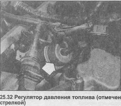
Fuel pressure control
32. The fuel pressure regulator is located between injectors No. 3 and No. 4 (photo).
33. Wrap a rag around the regulator to absorb spilled fuel.
34. Disconnect the fuel and vacuum hoses and remove the regulator.
35. Installation is carried out in the reverse order.
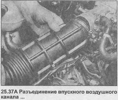
Throttle cover
36. Disconnect the negative battery cable.
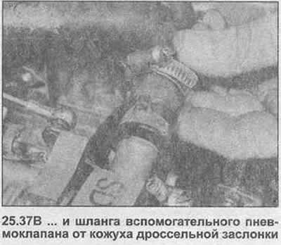
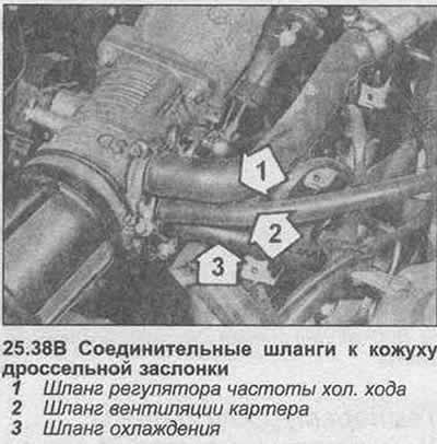
37. Loosen the clamps, disconnect the air inlet and auxiliary air valve hose (photo).
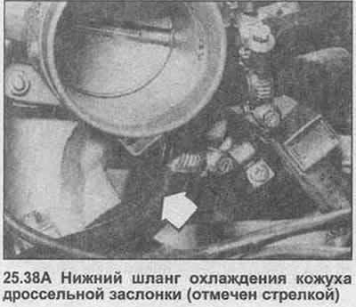
38. Install the clamp on the cooling hoses, then disconnect them from the casing (photo).
39. Disconnect the accelerator cable and lowering cable (kickdown) automatic transmission and medium speed control cable.
40. Disconnect wiring from throttle switch.
41. Disconnect the throttle return spring.
42. Disconnect the crankcase ventilation hose.
43. Remove the nuts and remove the throttle body from the intake manifold. Remove the gasket.
44. Installation is carried out in reverse order, install a new gasket and adjust the cables as necessary. Top up the coolant level.
Visitor comments