
See the remark given in Chapter 25.
Throttle switch
1. See Chapter 25 paragraphs 1-3.
Fuel injectors
2. Disconnect the negative battery cable.
3. Disconnect wiring from idle speed control. Disconnect the hoses and remove the regulator.
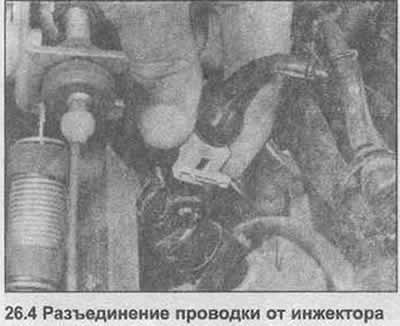
4. Disconnect the wiring from the injectors (photo).
5. Turn off four bolts fixing a highway of distribution of fuel to an inlet collector.
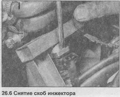
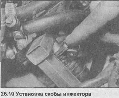
6. Using a screwdriver, remove the brackets that secure the injectors to the distributor line (photo).
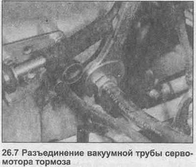
7. Unscrew the union nut, disconnect the brake servomotor vacuum pipe from the intake manifold (photo).
8. Remove the fuel feed pipe hanger.
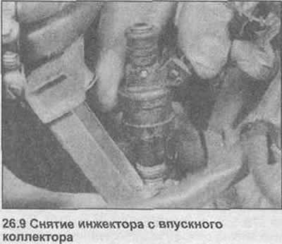
9. Loosen the injectors on the distributor line and remove them from the intake manifold (photo). Check the injectors as described in Chapter 25.
10. Installation is carried out in the reverse order, if necessary, replace the injector O-rings (photo).
11. Loosen the bracket, disconnect the air duct from the air flow sensor.
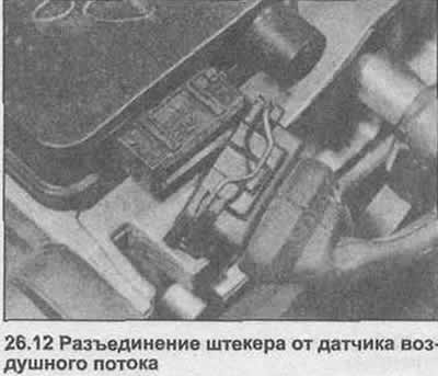
12. Disconnect the multi-pin plug (photo).
13. Release the spring clips, lift the airflow sensor and cover off the air cleaner housing.
14. If necessary, unscrew the sensor from the cover.
15. Wipe the air valve of the sensor, check that it moves freely.
16. Installation is carried out in the reverse order.
Control block
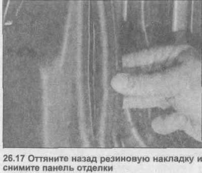
17. Pull back the rubber pad, remove the trim panel on the right side at the driver's feet (photo).
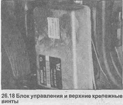
18. Remove the three fixing screws (photo).
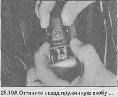
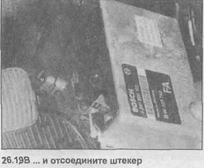
19. Pull back the spring clip, disconnect the multi-pin plug (photo). Take out the control unit.
20. Installation is carried out in the reverse order.
Temperature sensor
21. Be guided Chapter 25, paragraphs 18-22.
Idle speed controller
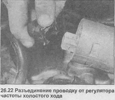
22. Disconnect the wiring from the back of the regulator (photo).
23. Loosen the brackets, disconnect the air hoses.
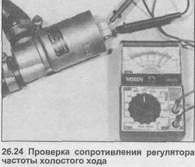
24. Connect an ohmmeter to the terminals of the regulator, the resistance should be 8 ohms (photo).
25. Installation is carried out in the reverse order.
Control relay
26 See Chapter 25, paragraphs 29-31.
Fuel pressure control
27 See Chapter 25, paragraphs 32-35.
Throttle cover
28. The procedure is essentially the same as that given in Chapter 25, paragraphs 36-44, except for disconnecting the auxiliary air valve hose.
Visitor comments