
Throttle body
Disconnect the negative battery terminal.
Release the clamp and disconnect the plug connector from the intake air temperature sensor. Do not pull on the wire during disconnection.
Loosen the screws securing the air duct to the throttle body and air mass meter, then remove it.
Disconnect the idle air control valve hose from the throttle body.
Disconnect the camshaft cover breather hose from the throttle body.
Disconnect the fuel tank vent valve vacuum hose from the throttle body.
Disconnect the coolant hoses from the throttle body. Refrigerant may leak, so pinch the open ends of the hoses to prevent leakage.
Loosen the clamp and disconnect the connector from the throttle position sensor.
Loosen the clamp, then disconnect the cable end swivel from the throttle lever.
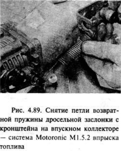
Remove the throttle cable bushing from the bracket located on the intake manifold, then unhook the throttle return spring hook from the bracket. If necessary, you can unhook the spring from the bushing in the throttle control system, noting its location for easier assembly (pic. 4.89).
Make sure all hoses and wires are disconnected and will not interfere with throttle body removal.
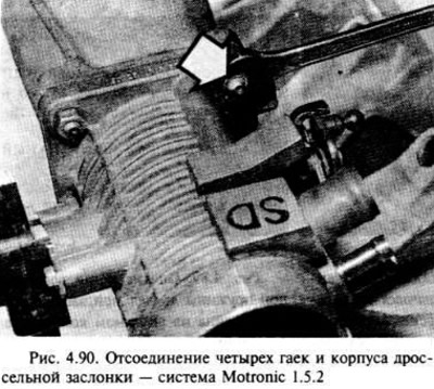
Remove the four nuts and remove the throttle body from the intake manifold. Access to the lower nuts may be restricted due to the two fuel hoses and may therefore need to be moved back. Try not to stretch the hoses.
Remove the gasket.
If desired, you can remove the throttle position sensor from its housing, as described in this section.
Installation
Installation is carried out in the reverse order of removal, taking into account the following.
Where required, install the throttle position sensor as shown below.
Thoroughly wipe the mating surfaces of the throttle body and intake manifold and install the body with a new gasket.
Make sure. that all wires and hoses are connected correctly.
Check and, if necessary, add coolant to the correct level.
After finishing work, check and, if necessary, adjust the free play of the throttle cable, as indicated earlier.
Fuel injectors
Note: The seals on both ends of the fuel injectors must be replaced during installation.
Removing
Disconnect the negative battery terminal.
Remove the union nut and disconnect the brake servo vacuum hose from the intake manifold.
Remove the idle air control valve along with the hose as shown below.
Disconnect the fuel pressure regulator vacuum hose.
Disconnect the wiring harness from the fuel injectors and move it to the side, being careful not to pull on the wires. Pull the wiring shroud and squeeze the contact clamps to disconnect the wiring shroud from the injectors.
Place a rag under the fuel pressure regulator. then relieve the pressure in the fuel system by slowly loosening the screws securing the fuel supply hose to the pressure regulator. Possible leakage, take fire precautions.
Remove the four screws from the brackets holding the fuel distributor to the intake manifold, then lift the distributor together with the injectors so that they can be removed. Try not to stretch the fuel hoses. Possible fuel leakage, take fire precautions.
To remove the injector from the fuel distributor, remove the metal clip with a screwdriver, then remove the injectors.
Fuel injectors cannot be repaired, there are no spare parts for them. The defective unit must be replaced with a new one.
Installation
Installation begins by replacing the seals on both sides of the fuel injector.
Installation is carried out in the reverse order of removal, taking into account checking that all hoses, tubes and wires are installed correctly.
Fuel pressure regulator - removal and installation
Disconnect the negative battery terminal.
For better access, remove the idle control valve as described later in this section, then disconnect the wiring from the fuel injectors and move it aside, being careful not to pull on the wires. Pull on the wiring shroud and squeeze the plug connector clip to disconnect the wiring shroud from the injectors.
Place a rag under the pressure regulator to soak up spilled fuel from the detachable regulator.
Slowly unscrew the screws and disconnect the fuel hoses from the regulator. Leaks possible, take fire precautions.
Disconnect the vacuum hose from the top of the regulator and remove the regulator.
Installation is carried out in the reverse order of removal.
Air mass meter
Note: A new seal must be applied during installation and a sealant will be required to cover the bolt threads.
Removing
Disconnect the negative battery terminal.
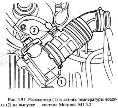
Loosen the clamp and disconnect the plug connector from the temperature sensor located in the pipeline. During disconnection, do not pull on the wire.
Disconnect the connector from the air mass meter in the same way.
Loosen the screws securing the air line to the throttle body and flow meter, then remove the air line.
Remove the air cleaner cover along with the flow meter as described earlier.
Remove the two bolts and remove the flow meter from the air cleaner cover. Remove the sealing ring.
Installation
Installation is in the reverse order of removal, however, a new O-ring must be used when installing the flow meter on the air cleaner cover and coat the bolt threads with sealant.
Throttle position sensor
Operation as described in the previous section for Multec multi-point fuel injection engines, assuming that the sensor is attached with two screws.
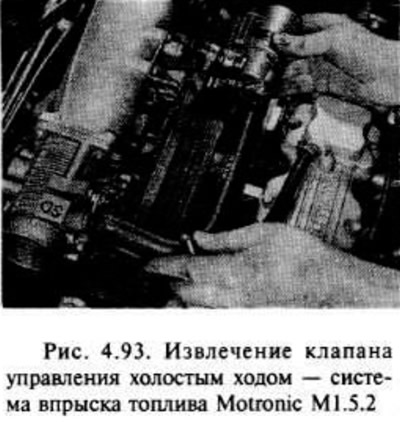
Idle control valve - removal and installation
Disconnect the negative battery terminal.
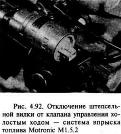
Loosen the clamp and disconnect the plug from the idle air control valve (pic. 4.92).
The valve can be removed with its hoses or separately, leaving the hoses in place.
Loosen the clamp screws, then disconnect the hoses and remove the valve (pic. 4.93).
Installation is carried out in the reverse order of removal.
Crankshaft Position/Speed Sensor
The procedure for performing the work is as indicated earlier in the section "Components of the Multec Single Point Injection System" for 1.8 l engines.
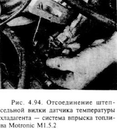
Refrigerant temperature sensor
The procedure is as described in the section "Components of the Multec Single Point Injection System". However, note that the sensor is located in the thermostat housing on the side of the engine on the intake manifold side, under the alternator top bracket (pic. 4.94).
Intake air temperature sensor
The procedure is as described in the section "Components of the Multitec system" for engines with Multec multi-point fuel injection, however, it must be remembered that the sensor is located in the air duct between the intake manifold and the flow meter. Be careful not to damage the air line.
Exhaust oxygen sensor
The procedure is as described in the section "Components of the Multitec system" for engines with single point fuel injection, however, note that the sensor is installed in the front section of the exhaust tract and can be accessed from under the vehicle. If desired, you can raise the front of the car, securely fastening it to the racks under the bridge.
Electronic control unit
The procedure is as described in the section "Components of the Multitec system" for engines with single point fuel injection, regardless of that. which refers to the main control unit and program memory.
Evaporative Emission System Components
See the last section in parts "WITH" this chapter.
Visitor comments