
Air box
Removing
Loosen the screw securing the air duct to the left side of the air mass meter.
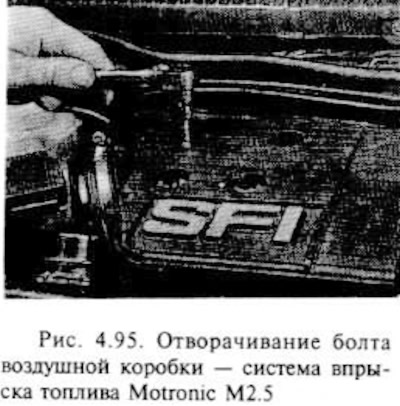
Unscrew the four bolts securing the air box to the throttle body with a socket wrench (pic. 4.95).
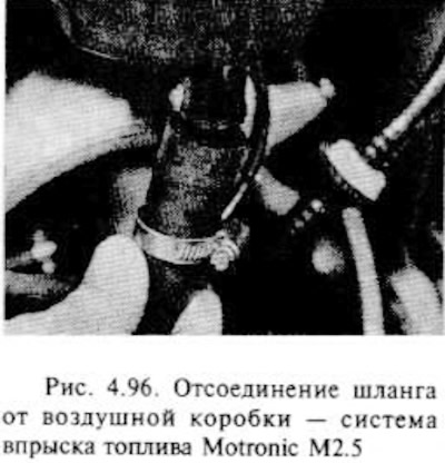
Remove the airbox from the top of the throttle body and disconnect the hose from the base of the airbox (pic. 4.96).
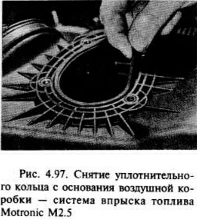
Remove the airbox and remove the O-ring from its base if it is loose on the surface (pic. 4.97).
Installation
Before installing, remove the O-ring from the base of the airbox, if you have not already removed it.
Check the O-ring and if it is damaged or worn, replace it.
Thoroughly wipe the O-ring area in the air box, then lubricate the end face well with an appropriate sealant (Vaushall/Opel N 15 04 851 or equivalent).
Install the o-ring to the air box, making sure it is installed correctly, then reassemble in the reverse order of removal.
Main throttle body
Removing
Disconnect the negative battery terminal.
Remove the air box/air flow meter assembly from the top side of the throttle body as directed in this section.
Release the clip and disconnect the connector from the throttle position sensor. When disconnecting, pull on the plug, not on the wire.
Unscrew the nut and disconnect the fuel hose bracket from the left side of the throttle body.
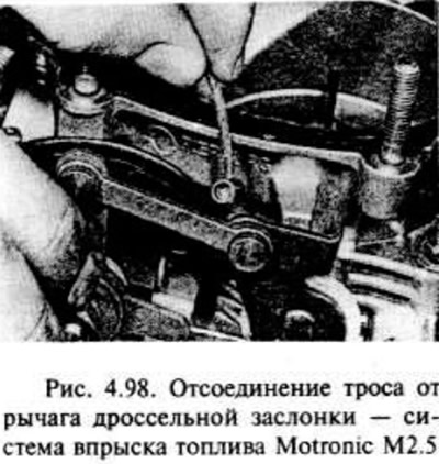
Disconnect the end of the cable from the throttle lever (pic. 4.98).
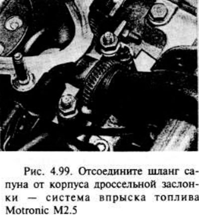
Disconnect the breather hose from the front of the throttle body (pic. 4.99).
Make sure all hoses, tubes and wires are disconnected and cleared away from the throttle body.
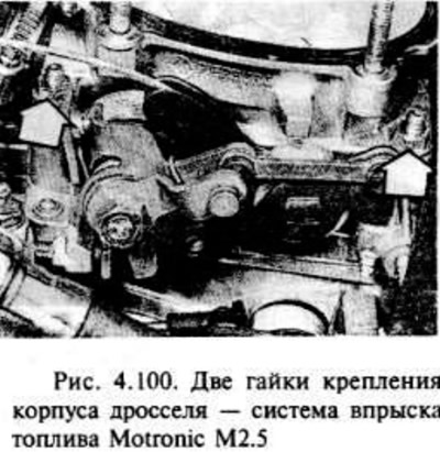
Remove the four nuts and remove the throttle body from the intake manifold. Remove gasket (pic. 4.100).
If desired, you can remove the throttle position sensor from its body, as described in this section.
Do NOT, under any circumstances, attempt to adjust the throttle control lever and linkage system. If the system requires adjustment, take the problem to a Vauxhall/Opel dealer.
Installation
Installation is carried out in the reverse order of removal, taking into account the following.
Before installing the throttle body, check the adjustment of the throttle position sensor, as indicated below in the subsection '' Throttle position sensor".
Carefully remove dirt from the mating surface of the throttle body with the housing of the electronic traction control control unit (RTU) and install a new gasket.
Check if all hoses, pipes and wires are properly connected.
Install the airbox as previously stated.
At the end of work, check and, if necessary, adjust the free play of the throttle cable, as indicated earlier in the appropriate section.
Casing of the neutron control unit of the RTU system
See the relevant section below.
Fuel injectors
Removing
Disconnect the negative battery terminal.
Remove the airbox as previously stated.
Place a rag under one of the fuel hose fittings located on the fuel rail to soak up escaping fuel.
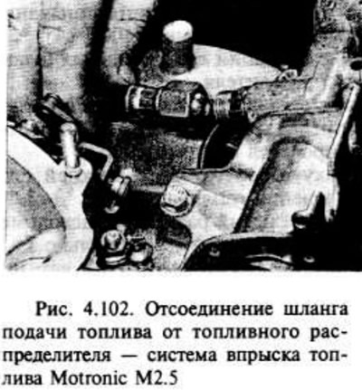
Slowly unscrew the fuel line fitting to reduce the pressure in the fuel line. then disconnect the hose from the fuel distributor. Possible fuel leakage, so take fire-fighting measures. Clamp the end of the fuel hose to prevent dirt from entering it and fuel leakage (pic. 4.102).
Repeat these steps for the rest of the fuel distributor hoses.
Disconnect the two breather hoses from the back of the camshaft cover. Disconnect the large hose from the throttle body and remove.
Disconnect the vacuum tube from the top side of the fuel pressure regulator.
Disconnect the plug from the air mass meter and remove the O-ring.
Disconnect the connector from the throttle position sensor.
Disconnect the end of the cable from the throttle lever, then remove the cable bracket bolts on the intake manifold and slide the bracket out of the way.
Disconnect the wiring from the fuel injectors and take it to the side, being careful not to pull the wires. Lift the wiring harness shroud and squeeze the plug connector clips to release the shroud from the injectors.
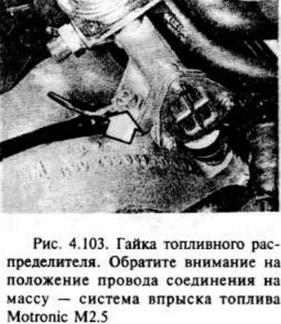
Unscrew the two nuts securing the fuel distributor and remove it together with the injectors from the intake manifold. Note the position of the ground wires on the distributor studs (pic. 4.103).
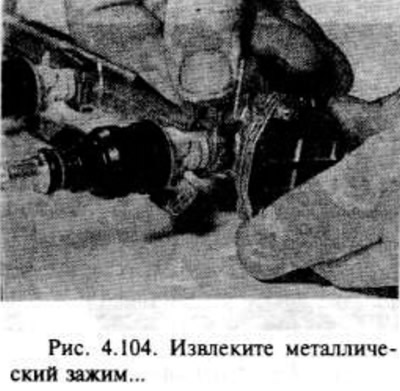
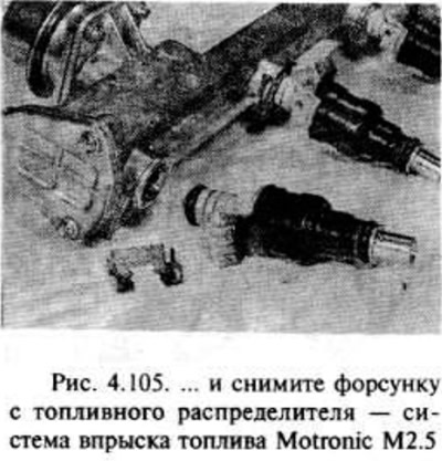
To remove the injector from the fuel distributor, remove its metal clip, the injector itself (pic. 4.104, 4.105).
Installation
Begin installation by replacing the old seals with new ones at the ends of the fuel injectors.
Further installation is carried out in the reverse order of removal, taking into account the following.
Make sure all hoses, wires and tubes are properly connected.
Install the airbox as previously stated.
After finishing work, check and. if necessary, adjust the throttle cable free play as described earlier in "Throttle cable".
Fuel pressure control
Removing
Disconnect the negative battery terminal.
Remove the air box from the top side of the throttle body as above.
Release the clamp and disconnect the plug connector from the air mass meter. When disconnecting, pull on the plug, not on the wire. If required, remove the O-ring.
Release the clip and disconnect the connector from the throttle position sensor.
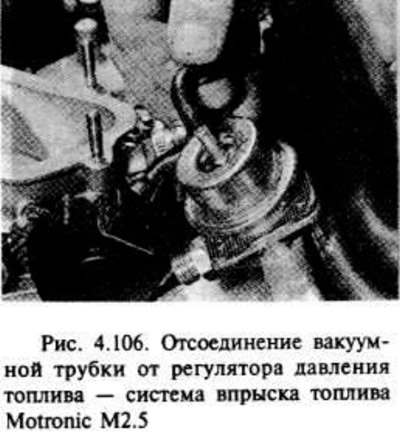
Disconnect the vacuum tube from the top side of the fuel pressure regulator (pic. 4.106).
Place a rag on the floor of the fuel line fitting located on the fuel distributor, then reduce the pressure in the fuel system by slowly unscrewing the fitting. Possible fuel leakage, so take fire precautions. Tighten the fitting after depressurizing.
Place a rag under the regulator to absorb escaping fuel while removing the regulator.
Using a wrench, unscrew the Tox bolts (with recessed head), then remove the regulator. Due to possible fuel leakage, take fire safety measures
Installation
Installation is carried out in the reverse order of removal, taking into account the following.
Check if all wires, tubes and hoses are properly connected.
Install the airbox as previously stated.
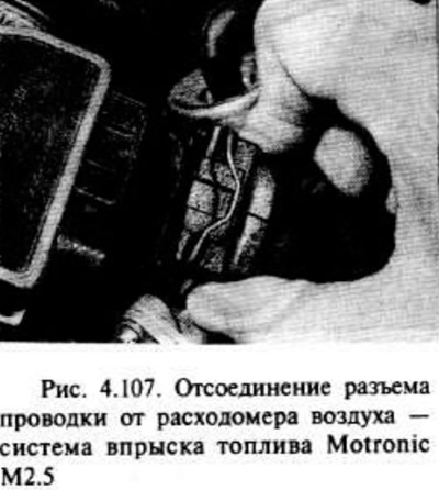
Air mass meter - removal and installation
Disconnect the negative battery terminal.
Release the clamp and disconnect the plug connector from the flowmeter. Pull on the plug, not the wire. Remove the o-ring if necessary (pic. 4.107).
Disconnect the screws and wiring harnesses from the flowmeter, then remove it.
Installation is carried out in the reverse order of removal. Check the condition of the O-ring on the plug connector and replace it if necessary.
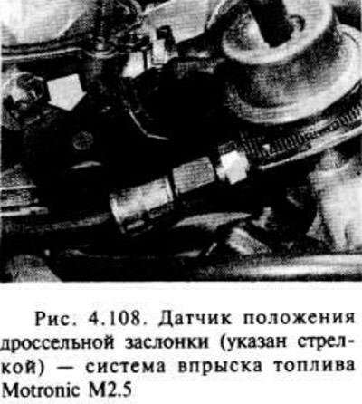
Throttle position sensor - removal and installation
Disconnect the negative battery terminal.
Remove the airbox and flow meter as previously noted.
Release clip and disconnect plug from throttle position sensor (pic. 4.108).
Remove the two screws and remove the sensor from the throttle body.
Install the sensor, but before tightening the screws, adjust its position as follows.
Turn the sensor housing counterclockwise until it stops, then tighten the screws.
When the throttle valve opens, a characteristic click should be heard, it should be repeated during the closing of the valve.
If necessary, adjust the position of the sensor so that a click is heard as soon as the throttle starts to open.
Install the air box as above.
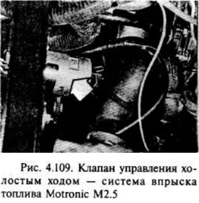
Idle control valve - removal and installation
Disconnect the negative battery terminal.
Loosen the clamping screw and disconnect the hose from under the air box located on the throttle body. Remove the clamp from the hose.
Engage the handbrake, then jack up the front of the vehicle and secure it with a jackstand under the axle.
Remove the lower engine mudguard as directed in chapter 11.
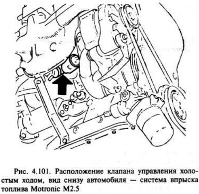
Working under the vehicle, disconnect the connector from the idle air control valve, which is located under the intake manifold above the starter motor (pic. 4.109).
Loosen the clamping screw and disconnect the other end of the idle air control valve hose from the intake manifold, then move the valve down with the hoses.
If the hoses must be removed from the valve, mark their location before removal so that they can be reinstalled correctly later. Once the valve is installed, it is very difficult to change the position of the hoses.
Installation is in the reverse order of removal, but make sure the valve is installed horizontally and the wires are routed over the coolant hose. If the wires are routed under this hose, the valve may tilt downward, which in turn may compress or rupture the air hose to the intake manifold.
Crankshaft Position/Speed Sensor
Operating procedure: as indicated in the section "Components of the Multitec system" for engines with a displacement of 1.8 liters.
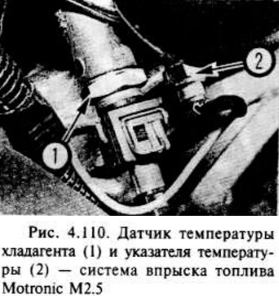
Refrigerant temperature sensor (precipitating liquid)
Operating procedure: as indicated in the section "Components of the Multitec system" for engines with single point fuel injection, however, please note. that the sensor is located in the thermostat housing on the exhaust manifold side of the engine (pic. 4.110).
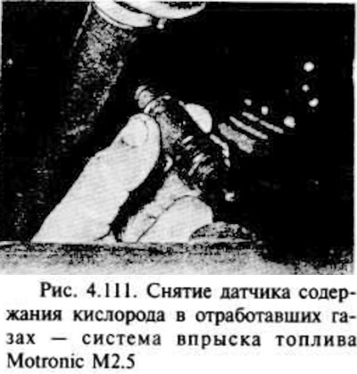
Exhaust oxygen sensor
Operating procedure: as indicated in the section "Components of the Multitec system" for engines with single point fuel injection, however note that the sensor is located in the front section of the exhaust line and can be accessed from under the vehicle after removing the lower engine mudguard hatch cover. If desired, raise the front of the vehicle, securing it securely to the stand under the drive axle (pic. 4.111).
Knock sensor - removal and installation
The sensor is located on the underside of the cylinder block intake manifold under the idle air control valve and unless the intake manifold is removed it will only be accessible from under the vehicle.
Disconnect the negative battery terminal.
Engage the handbrake, then jack up the front of the vehicle and secure it to a jack stand under the drive axle.
Remove the lower engine mudguard as directed in chapter 11.
Disconnect the sensor connector.
Turn away a bolt and remove the gauge from the block of cylinders.
Installation is carried out in the reverse order of removal, however, make sure that the sensor and its installation site are absolutely clean and that it is securely fastened. Failure to comply with these requirements can lead to a malfunction of the engine, since an incorrectly installed sensor will not register the appearance of knocking and it will not be possible to correct the ignition.
Electronic control unit
Operating procedure: as indicated in the section "Components of the Multitec system" for engines with single point fuel injection, regardless of the instructions regarding the main control unit and the program memory.
Evaporative Emission System Components
See the relevant section in parts "WITH" this chapter.
Visitor comments