
Note: Hydraulic fluid is poisonous; If liquid gets on the skins, rinse immediately with plenty of water. Some types of hydraulic fluid are flammable and may ignite on contact with hot components. Also, the brake fluid absorbs moisture from the air - the old fluid may be contaminated and unsuitable for further use. Always use the recommended type of fluid from a sealed container.
General description
1. On later models, a new type front brake caliper is fitted.
Front brake pads (ATE support) - inspection and replacement
Warning: Replace both sets of front brake pads at the same time - never change pads on only one wheel as this can cause uneven braking. Please note that the dust generated during pad wear may contain asbestos, which is harmful to health. Never blow it out with compressed air. Do not use petroleum-based solvents to clean parts of the brake system. Use only methyl alcohol.
2. Apply the handbrake, then jack up the front of the vehicle and support it on axle stands. Remove both front wheels.
3. Thickness of brake pads (friction material and base plate) can be measured through a slot in the caliper. If any of the pads have worn less than the specified minimum thickness (See Section 9 of the Specifications), all pads must be replaced as a set on this axle. However, a much more complete check can be made if the caliper is removed first, as follows.
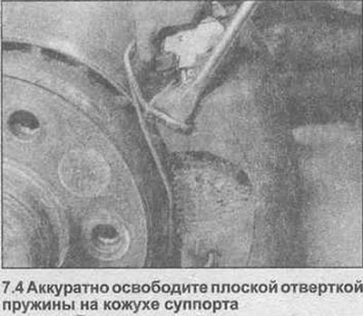
4. Carefully release the springs and remove them from the outside of the caliper body (photo).
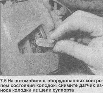
5. On vehicles equipped with a monitoring device, unfasten the pad wear sensor through the slot in the caliper (photo).
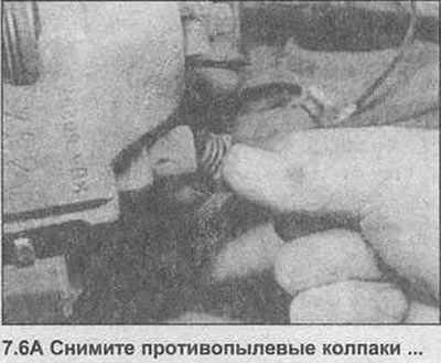
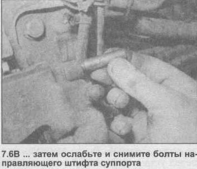
6. Remove the dust caps from the caliper drive pin bolt holes, then loosen and remove the two drive pin bolts and remove them from the caliper (photo).
7. Pull the caliper off the brake disc and unfasten the inner shoe from the caliper piston. Tie the caliper to the suspension strut using a suitable piece of wire, without bending the flexible brake high pressure line tube.
8. Remove the outer pad from the caliper mounting bracket.
9. First measure the thickness of each brake pad (friction material and base plate). If any pad is worn at any point to the specified minimum thickness (see Section 9 of the Specifications), all four pads must be replaced. The pads should also be replaced if any are contaminated with oil or grease; there is no satisfactory way to degrease the friction material if it is contaminated. If any of the brake pads are worn unevenly or contaminated with oil or grease, find out and correct the cause before reassembly. On vehicles equipped with pad monitoring, if the pad wear sensor has been in contact with the brake disc, it must also be replaced.
10. If the brake pads are still serviceable, gently clean them using a clean, wire brush. Sand the grooves in the friction material and remove any large embedded dirt or grime particles. Carefully clean the location of the pad in the caliper body and mounting bracket. Check that the guide pins are free and easily tighten the upper bushings in the caliper. Inspect the dust seal around the piston and the piston for signs of leakage, corrosion, or damage.
11. If new brake pads are being installed, the caliper piston must be placed back into the cylinder to make room. Either use a G-clamp or a similar tool, or use suitable pieces of wood as leverage. If the master cylinder hydraulic fluid reservoir has not been emptied, there should be no leaks, but watch the fluid level closely as the piston retracts. If the liquid level rises above the maximum level mark, the excess must be removed with a syringe.
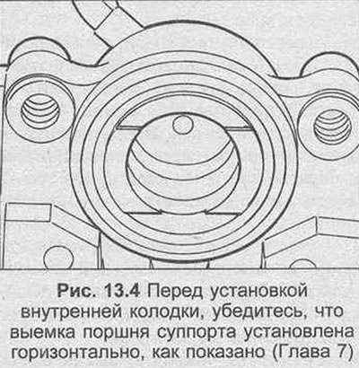
12. Before installing the inner pad, check that the notch on the caliper piston is horizontal to the caliper body (see fig. 13.4). If necessary, rotate the piston until the notch is correctly seated.
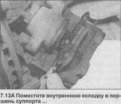
13. With the piston properly installed, place the inner pad in place and install the outer pad in the caliper mounting bracket. Check that the friction material is facing the brake disc (photo).
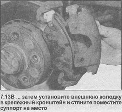
14. Place the caliper in place on the brake disc and outer pad.
15. Completely clean the threads of the pilot pin bolts, then coat with a suitable blocking compound. Install the bolts in the holes of the caliper, then tighten them, tightening torque, regulated specification and install dust caps.
16. On vehicles equipped with a monitoring system, fasten the pad wear sensor in place on the pad. If a new sensor is installed, then take the wiring from the original sensor.
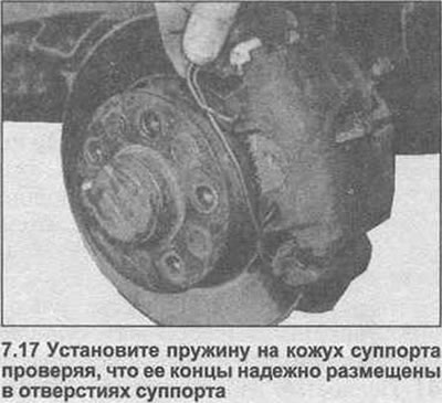
17. Install the caliper spring, making sure its ends are securely seated in the holes in the caliper body (photo).
18. Check that the caliper body moves smoothly on the guide pins, then depress the brake pedal several times until the pads make contact with the brake disc and normal pedal pressure is restored.
19. Repeat the above procedure on the remaining front brake caliper.
20. Install the wheels, then lower the vehicle to the ground and tighten the wheel bolts to the specified torque specification installation.
21. Check the hydraulic fluid level.
Front brake caliper (ATE support) - removal, reassembly and installation
Note: Before starting work, see the note at the beginning of this Chapter regarding the dangers of hydraulic fluid and asbestos dust.
Removing
22. Block the rear wheels, tighten the handbrake, then jack up the front of the car and fix it on axle stands. Remove the corresponding front wheel.
23. To reduce fluid loss, remove the master cylinder reservoir cap and plug the holes with a piece of polyethylene, or, using a G-clamp or similar tool on the brake high pressure line pipe, pinch the flexible hose.
24. Clear area round connection, then turn off a bolt of connection of a line of a highway of a high pressure of a brake system and disconnect a hose from a support. Seal the end of the hose and caliper openings to prevent dirt from entering the hydraulic system. Discard the gaskets; they should always be replaced after the caliper has been removed.
25. On vehicles equipped with a monitoring system, unfasten the pad wear sensor from the caliper slot.
26. Carefully unfasten the large spring and remove it from the outside of the caliper body.
27. Remove the dust caps from the caliper guide pin bolt holes, then loosen and remove the two bolts and remove them from the caliper.
28. Carefully lift the caliper assembly away from the brake disc and remove the inner pad from the caliper piston. Note that the outer pad does not have to be removed and can be left in the caliper mounting bracket.
Bulkhead
29. Place the caliper on the bench, wipe off all traces of dust and dirt.
30. Partially slide the piston out of the caliper body and remove the dust seal. The piston can be removed by hand, or, if necessary, pushed out by applying compressed air to the connecting bolt hole. This requires low pressure, such as that created by a foot pump.
31. Using a small screwdriver, pry out the hydraulic piston seal, being careful not to damage the caliper bore.
32. Knock out the guide bushings from the caliper body using a suitable socket.
33. Thoroughly clean all components using only methanol or clean brake fluid. Never use mineral solvents such as benzine or paraffin as they attack the rubber components of the hydraulic system. Dry the components immediately using compressed air or a clean, lint-free cloth. Use compressed air to blow out the flush grooves.
34. Check all components and replace worn or damaged ones. Pay special attention to the cylinder bore and piston; they need to be replaced (note that this means replacing the complete case assembly), if they are notched, worn or corroded. Similarly, check the condition of the guide pins and their bushings; both guide pins must not be damaged. If there is any doubt about the condition of any component, replace it.
35. If the assembly is fit for further use, take a new piston and dust seal and a tube of brake cylinder paste (number 90 295 751).
36. Apply a small amount of brake cylinder paste to the surfaces of the caliper bore, piston and piston seal.
37. Install the piston seal into the caliper bore using only the power of your fingers. Install a new dust seal on the piston, then carefully place the piston into the caliper bore, twisting it straight into the bore.
38. Push the piston all the way into the bore, then rotate the piston so that the notch is horizontal to the caliper body (see fig. 13.4). When the piston is properly seated, press the dust seal into the groove on the caliper body.
39. Lightly grease the caliper guide bushings with soapy water, then press them into place in the caliper body. Installation
40. Place the pads in place on the caliper piston, then install the caliper onto the brake disc and outer pad.
41. Completely clean the threads of the pilot pin bolts and lightly coat with a suitable blocking compound. Install the bolts in the holes of the caliper, then tighten them, tightening torque, regulated specification and install dust caps.
42. On vehicles with a monitoring system, secure the sensor in place on the block.
43. Install the caliper spring and make sure its ends are securely seated in the holes in the caliper body.
44. Place a new gasket on each side of the hose coupler and install the brake high pressure pipe connection bolt. Check that the connection of the high pressure line pipe of the brake system is correctly installed against the protrusion on the caliper and tighten the connection bolt with the tightening torque specified specification.
45. Remove the brake high pressure line clamp, if used, and bleed the hydraulic system as described in Section 9. Note that, while ensuring the precautions described have been taken in order to minimize brake fluid loss, it should only be necessary to bleed the appropriate front brake.
46. Install the wheel, then lower the vehicle to the ground and tighten the wheel bolts to the specified torque specification.
Front brake caliper mounting bracket bolts (all models) – revised tightening procedure
47. On all front brake calipers, the bolts of the caliper mounting bracket - steering pivot are now first clamped with the tightening torque regulated specification, then rotated by the specified angle (see Specifications at the beginning of this Section). Also note that the bolt threads must be coated with a suitable blocking compound before installation.
48. The mounting bracket bolts must be replaced each time they are loosened.
Handbrake lever and cable (models with catalytic converter) - removal and installation
49. On models with a catalytic converter, the handbrake cable and lever can be removed and installed as described in the relevant Chapter 9. Note that in both cases, both catalytic converter heat shields must first be removed to gain access to the cable adjustment nut.
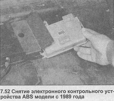
ABS electronic control (since 1989) - removal and installation
Removing
50. On the 1989 model year, the ABS electronic control unit is located under the front passenger seat. To remove the block, first disconnect the negative battery terminal.
51. Pull the passenger seat all the way forward to access the block on the back of the seat.
52. Open the plastic cover, then remove the control box from the back of the plastic cover (photo). Disconnect the wiring connector and remove the unit from the vehicle.
Installation
53. Installation is the reverse procedure of removal.
Visitor comments