


Contents: Disc brakes ⬇ Drum brakes ⬇ Vacuum booster ⬇ Parking brake ⬇ Pressure regulator valve in the…⬇
Remember that the dust generated by the brake mechanisms may contain asbestos, which is extremely harmful to human health. Never blow off dust with compressed air or inhale it; wear a protective mask or respirator when servicing the mechanisms. Never use gasoline or petroleum-based solvents to wipe brake system components - use only branded cleaning agents or methyl alcohol!
More detailed illustrative material on brake mechanisms is given in Chapter Brake system.
The condition of the brake system components, in addition to the regular checks specified in the routine maintenance schedule, must be assessed every time the wheels are removed or when signs of a malfunction in the brake system occur.
The following symptoms may indicate faulty brake components:
- When braking, the car loses directional stability (there is a pull to one side);
- When braking, the brakes make a squealing or squeaking noise;
- The foot brake pedal travel increases excessively;
- When pressing the brake pedal, pulsations are felt;
- There are traces of brake fluid leakage (usually on the inner surface of wheel rims and tires).
1. Loosen the wheel nuts.
2. Jack up the car and place it on supports.
3. Remove the wheels.
Disc brakes
The support of each brake mechanism is equipped with two pads (internal and external). The ends of the pads are clearly visible through a special viewing window in the caliper body after removing the wheel.
Thickness of brake pad with base
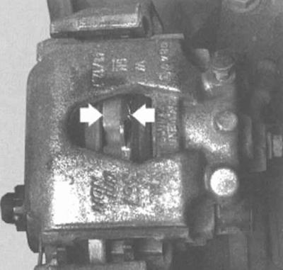
The residual thickness of the friction lining of the inner shoe is assessed visually through the inspection window of the caliper. If the linings are worn beyond the permissible limit (see Vehicle settings and routine maintenance), it is necessary to carry out a comprehensive replacement of the brake pads.
1. If it is difficult to visually assess the remaining thickness of the pads, or there is a need for a more detailed inspection of the pads, remove the caliper and take out the pads for a more detailed examination (see Chapter Brake system).
2. After the pads have been removed from the caliper, clean them with a special agent and check the remaining thickness of the linings with a ruler or a caliper equipped with a vernier.
(Article published on the website: opelbook.ru)
3. Use a micrometer to measure the thickness of the brake discs. Compare the measurement results with the standard requirements (see Vehicle settings and routine maintenance). If the thickness of any of the discs is outside the permissible range, replace it (see Chapter Brake system). If the disk thickness is normal, check its general condition. Pay attention to such defects as deep scratches, grooves, scuffs, traces of overheating, etc., if necessary, remove the disk and have it turned (see Chapter Brake system).
4. Before reinstalling the wheels, inspect all brake lines for signs of damage, wear, degradation due to aging of the material, signs of leaks, bends, twists and other deformations (especially near the connection points of flexible brake hoses to the brake calipers). Check that the hose clamps are securely fastened. Make sure that none of the brake hoses come into contact with sharp corners of adjacent body parts, exhaust system components, or suspension components (at any steering wheel position). If necessary, make appropriate repairs or adjust the line routing. Replace defective components (see Chapter Brake system).
Drum brakes
1. When checking the rear drum brakes, make sure the parking brake is released, then tap the outside of the drum with a soft-faced hammer to loosen the fit.
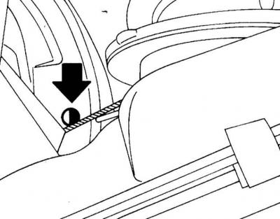
2. Remove the rubber cap of the inspection hole on the rear brake shields and shine a flashlight into the hole. Check the thickness of the linings. The wear limit has been reached if the lining has a thickness of 2.5 mm (without metal backing).
Brake adjustment thickness assessment hole
Never blow brake dust off the surface of components with compressed air or inhale it - the dust may contain asbestos, which is harmful to health!
3. If necessary, perform a complete replacement of the shoes. The shoes are also subject to replacement if cracks, polished to a shine areas of the linings, or traces of brake fluid are detected.
The brake pads of the entire axle must be replaced.
4. Make sure that all springs of the brake mechanism assembly are connected correctly and in good condition (see Chapter Brake system).
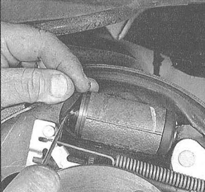
5. Check the assembly components for signs of brake fluid leaks. Using your finger or a small screwdriver, gently pry the rubber boots off the wheel cylinder at the top of the shoes. Any signs of leaks in these areas require immediate refurbishment of the cylinder assembly (see Chapter Brake system). Also check all brake hoses and their fittings for signs of leaks.
Checking the wheel cylinder for signs of brake fluid leaks
6. Wipe the inside of the drum thoroughly with a clean cloth soaked in methylated spirits. Avoid inhaling asbestos-containing dust.
7. Inspect the working surface of the drum for cracks, burrs, traces of overheating and other damage. If the defects cannot be removed by treating the surface with fine-grained sandpaper, the drum should be given to a car service workshop for turning.
8. Repeat the procedure for the opposite brake components. Replace the drums, secure the wheels and lower the vehicle to the ground.
Vacuum booster
The proper functioning of the brake booster is checked from the driver's seat.
1. With the foot brake pedal fully depressed, start the engine - the pedal should still fall a little.
2. With the engine running, press the foot brake pedal several times. The pedal travel should remain constant.
3. Press the pedal, turn off the engine and continue to hold the pedal pressed for about another 30 seconds, during which time it should neither fall lower nor rise.
4. Start the engine again, let it run for a minute, then turn it off again. Press the pedal firmly again several times - the stroke should decrease with each stroke.
5. If the result of the described check is negative, the brake booster servo drive must be replaced (see Chapter Brake system).
Parking brake
The parking brake is controlled by a lever installed between the front seats. Pull the lever until it stops, counting the number of clicks of the ratchet mechanism. If the number of clicks is outside the permissible range (see Vehicle settings and routine maintenance), the parking brake drive is subject to adjustment (see Chapter Brake system).
Alternatively, the parking brake can be checked for proper operation by parking the vehicle on a downhill section of the road and holding it still with the parking brake with the gearbox in neutral. If the brake does not hold the vehicle when the lever is pulled the required number of clicks, it must be adjusted (see Chapter Brake system).
Pressure regulator valve in the hydraulic circuits of the rear wheel brake mechanisms
Since there are two diagonally located brake circuits, two pressure regulator valves are required. The regulator valve ensures a slower increase in the pressure of the brake fluid going to the rear brake mechanisms than the brake fluid going to the front brake mechanisms. This eliminates excessive braking force on the rear wheels and increases the stability of the car when braking.
The brake force regulator with delay is installed in the lower part of the car above the rear suspension and is controlled via the rear suspension spring. Before checking the regulator operation, check the brake fluid pressure on the supply to the rear and front brake mechanisms. Regulator valves are replaced only in pairs. The designation of the regulator installation side is stamped on its body.
Location of control valves
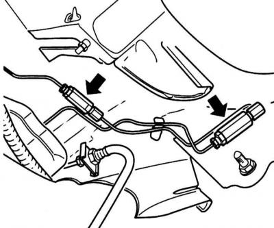
The serviceability check and adjustment of the pressure regulator valve is carried out on an unloaded vehicle standing on its wheels (the fuel tank is half full).
Checking the correct functioning
1. Have an assistant watch the pressure regulator valve. Press the brake pedal firmly and release it quickly.
2. In this case, the lever (1) of the control valve should move. If the lever does not move, replace the regulator, contacting a service station for assistance.
Control components of the control valve
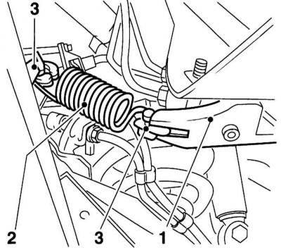
1 - Lever
2 - Tension spring
3 - Supports
Adjustment
1. Press the lever (1) in the direction of vehicle movement until it stops. The tension spring (2) must lie in the plastic supports (3) without any gap or tension (refer to illustration).
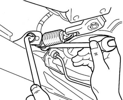
2. On models Hatchback to adjust, loosen the adjusting bolt and move it so that the spring fits without gap or tension.
Loosening the adjusting bolt
3. On models Combo to adjust, loosen the spring retainer and move it so that the spring fits without gaps or tension.
Weakening of the holder
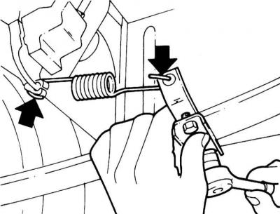
4. Tighten the mounting bolt with force 20 Nm.
Visitor comments