
External lamp units - removal and installation
Rear combination lamps
1. On Sedan models, open the trunk lid, then detach the corresponding trunk trim panel to access the lamp unit. Press the two lamp holder retainers and remove the holder from the lamp unit. Unscrew the four mounting bolts, and remove the lamp unit from the car.
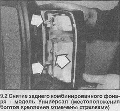
2. On Estate models, from inside the luggage compartment, turn the latch and open the corresponding lamp cover. Press the locking devices and remove the lamp socket assembly. Unscrew the three mounting bolts and remove the lamp unit from the car (photo).
3. Installation is the reverse procedure of removal.
Front fog lights
4. Tighten the handbrake, then jack up the front of the car and fix it on axle stands.
5. Disconnect the wiring connector from the corresponding fog lamp, then loosen and remove the mounting bolts and remove the lamp from the rear of the bumper.
6. Installation is the reverse procedure of removal.
Side marker light repeater
7. Where necessary, remove the mudguard mounting screws, then loosen and remove the appropriate front wheel arch liner mounting bolts. Unzip the back of the insert to access the side repeater lamp wiring connector.
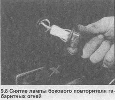
8. Disconnect the electrical wiring connector, then unfasten the mounting latches and remove the lamp from the wing (photo).
9. Installation is carried out in the reverse order.
Lamps - replacement
Passenger sun visor vanity mirror lamp
10. Lower the sun visor and use a small flathead screwdriver to carefully remove the bulb cover. Remove the lamp (s).
11. Installation is the reverse procedure of removal.
Headlight washer / wiper components - removal and installation
Wiper arm
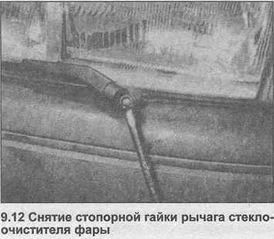
12. Raise the spindle trim, then loosen and remove the wiper arm retaining nut (photo). Remove the lever from the grooves of the spindle and remove from the vehicle.
13. Installation is the reverse procedure of removal. Check that the wiper blade is properly seated in the spindle grooves and that the lock nut is securely tightened.
Washer jet
14. Remove the wiper arm as described above.
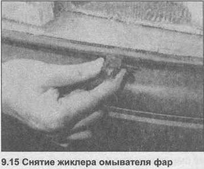
15. Push out the washer jet and disconnect it from the washer tube (photo). Tie a piece of twine to the tube to prevent it from falling behind the bumper.
16. Installation is the reverse procedure of removal.
Wiper motor
17. The wiper motor can be removed and installed as described in Chapter 32 of Section 12.
Washer pump
18. The pump is identical to the windshield washer pump, and can be removed and installed using the information given in Section 12, Chapter 33. Solenoid valve
19. Unscrew the windshield washer reservoir from the wheel arch and empty the contents into a suitable container.
20. Disconnect the valve wiring connector, then remove the valve from the tank.
21. Mark the hoses so as not to mix up during installation, then disconnect them and remove the valve from the car.
22. Installation is carried out in the reverse order. Check that the washer hoses are reconnected correctly. Finally, fill the tank with liquid.
Headlight Washer/Wiper Relay
23 See Section 12, Chapter 16.
Components of the central locking system - removal and installation
24. Disconnect the negative battery terminal.
Door Lock Motor - Pre-1988 Models
25. Remove the inner door trim panel as described in Section 11.
26. Remove the plastic water deflector from the door frame to gain access to the drive unit.
27. Loosen and remove its fixing screws from the thrust. Disconnect the electrical wiring connector and remove the drive motor from the door.
28. When installing, reconnect the wiring connector to the actuator, then connect the actuator to the linkage. Install the fixing screws of the servomotor unit, tightening them with your fingers at this stage. Adjust the drive motor as follows.
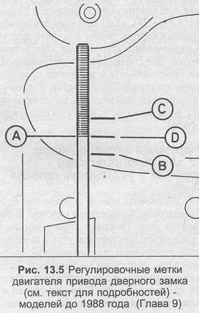
29. Using Fig. 13.5, make a mark «A» on the door lock button. Push the link to the closed position and make a mark on the door frame «IN» opposite the position of the label on the rod. Move the rod to the open position, and again make a mark on the door frame «WITH» opposite the position of the label on the rod. Third mark «D» on the door frame is done strictly between the marks «IN» And «WITH». Slowly move the linkage from the closed to the open position while listening for the drive motor switch. The switch should operate, with a characteristic audible click, when the rod is exactly halfway between the closed and open positions - that is, when the label «A» aligns with label «D». Adjust the position of the drive motor, then securely tighten the fixing screws.
30. If the drive motor is properly adjusted, install the plastic water-repellent shield into the door frame and install the door trim panel as described in Section 11.
Door lock motor - models since 1988
31. On models since 1988, remove the lock assembly as described in Section 11. Remove the two drive motor mounting screws, then disconnect the motor and remove it from the suspension.
32. When installing, reconnect the engine control lever to the linkage, then install the mounting screws, tightening them with your fingers only. Before installing the lock assembly, adjust the position of the drive motor as described in the appropriate next paragraph.
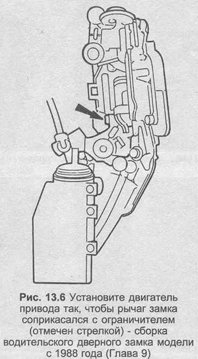
33. Press the drive control lever in the driver's door to the closed position and adjust the position of the servo motor so that the lock lever touches the stopper (see fig. 13.6). Lock the drive in this position and tighten the fixing screws securely.
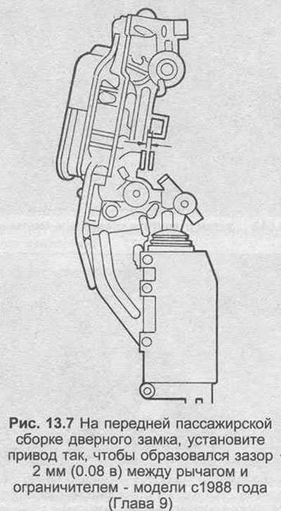
34. Press the control lever into the front passenger door drive motor and adjust the position of the motor so that a gap of 2 mm is formed between the lock lever and the limiter (see fig. 13.7). Lock the drive motor in this position and tighten the fixing screws securely.
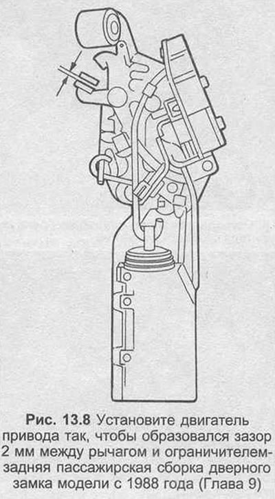
35. Rear passenger doors: press the control lever into the drive motor and in the closed position, adjust the position of the motor to a gap of 2 mm between the lock and the limiter (see fig. 13.8). Lock the drive motor in this position and tighten the fixing screws securely.
36. If the drive motor is properly adjusted, install the lock assembly to the door as described in Section 11.
Rear Door/Trunk Lid Motor
37. Open the trunk lid or tailgate, then loosen and remove the two drive motor mounting screws. Disconnect the drive from the linkage link, then disconnect the wiring connector and remove the drive motor.
38. When installing, connect the wiring connector, then connect the actuator control lever to the linkage linkage. Install the drive motor mounting screws and tighten them by hand at this stage. Adjust the position of the drive motor as follows.
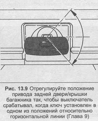
39. Insert the key into the lock and set the lock in a horizontal position. Slowly turn the key up and down while listening to the drive motor. The switch should operate with a characteristic click when the key is set to one of two positions relative to the horizontal line (see fig. 13.9). Adjust the position of the drive motor in this way, then securely tighten the fixing screws.
Fuel filler cap drive motor
40. From inside the luggage compartment, carefully remove the rear right trim panel until the drive motor is accessible.
41. Disconnect the electrical wiring connector from the rear of the engine, then unscrew the two mounting screws and remove the engine from the vehicle.
42. Installation is the reverse procedure of removal.
Control switch assembly
43. The control switch assembly consists of two microswitches mounted on the back of the lock cylinder. One switch is connected to the central locking system, the other is connected to the power window system.
44. To remove the switch, first remove the door trim panel as described in Section 11.
45. Pull back the plastic water shield to access the outside door handle.
46. Disconnect the electrical wiring from the microswitch assembly on the connector. Unfasten the switch assembly from the handle and remove it from the door.
47. Installation is the reverse procedure of removal.
Electronic control device
48. The electronic central locking control is located behind the trim panel on the driver's side (see Figure 12.6, «IN», Section 12).
49. To remove the block, remove the rubber pad and remove the trim panel from the driver's side.
50. Disconnect the electrical wiring connector, then unscrew the two mounting bolts and remove the control unit from the vehicle.
51. Installation is the reverse procedure of removal.
On-board computer components - removal and installation
52. Disconnect the negative battery terminal.
On-board computer
53. Remove the dashboard as described in Section 12.
54. Slide the on-board computer out of the panel and disconnect the wiring connector.
55. If a new trip computer is being installed, remove the program memory block from the original block and install in the new computer. If the computer display lamp is burnt out, take the computer to your dealer, as a special tool is required to replace the lamp.
56. Installation is the reverse of removal, noting that no pressure is allowed on the front of the computer to avoid damaging the indicators.
Trip computer switch
57. Remove an average facing from the console and disconnect a connector of electroconducting of the switch of the onboard computer. If the switch connector cannot be accessed through the trim slot, remove the fixing screws of the center console and lift the console slightly. See Section 11 for further information.
58. If the switch wiring connector is disconnected, press the switch securing latches and remove the switch from the casing.
59. Installation is the reverse procedure of removal.
Outside temperature sensor
60. The outside air temperature sensor is attached to the front bumper. To remove the sensor, unfasten it from the bumper and disconnect the wiring connector.
61. Installation is carried out in the reverse order.
Components of the speed controller - removal and installation
62. Disconnect the negative battery terminal.
Regulator block
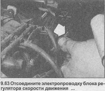
63. The regulator block is installed on the bulkhead of the engine compartment. To remove the unit, first disconnect the electrical wiring connector (photo).
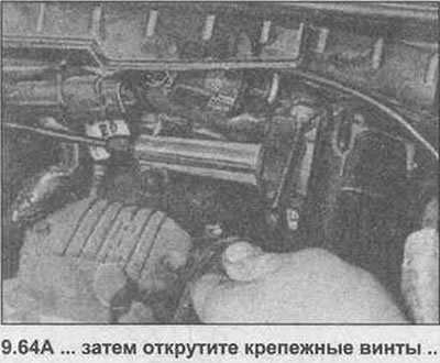
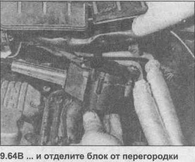
64. Unscrew the three fixing screws and disconnect the regulator block from the baffle (photo).
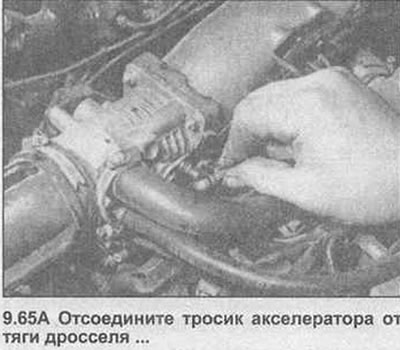
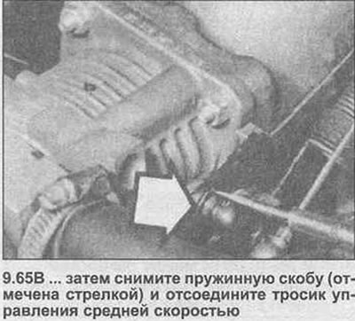
65. Separate the small spring clip and disconnect the spherical sector of the accelerator cable from the throttle rod. Carefully remove the spring clip with a lever and disconnect the medium speed control cable from the throttle link (photo). (See photo 9.73 for cable release method).
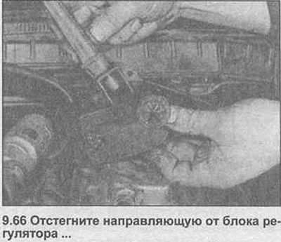
66. Screw the adjusting screw fully into the guide, then unfasten the guide from the regulator block (photo).
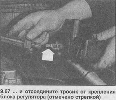
67. Pull the guide out of the regulator block and disconnect the medium speed control cable from the regulator block (photo). Remove the regulator block from the vehicle.
68. When installing, attach the cable fitting to the regulator block. Lock the guide into place in the regulator block.
69. Install the medium speed cable on the throttle link and secure with a spring clip. Reconnect the accelerator cable and secure with the spring clip.
70. Install the regulator block mounting screws and tighten securely. Reconnect the electrical wiring connector.
71. Adjust the accelerator cable as described in Section 3, then adjust the medium speed control cable as described in step 77.
Speed control cable
72. Follow the steps described above in paragraphs 63 to 67.
73. Release the cable cover mounting bracket from the throttle body and remove the cable from the engine compartment (photo).

74. If a new cable is being installed, unscrew the guide from the original cable's mounting nut, and thread it completely onto the new cable's mounting nut.
75. When installing, lock the cable cover into place on the throttle body, then follow steps 68 to 70.
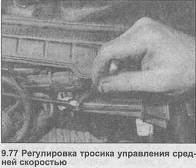
76. Adjust the throttle cable as described in Section 3, then adjust the speed control cable as follows.
77. Tighten the fixing nut of the guide until the slack of the cable is saved and the thrust starts to move only the throttle (photo). From this position, unscrew the mounting nut two full turns back along the guide so that there is a slight play in the cable.
Control block
78. The control unit is located behind the glove compartment at the end of the panel (photo) - also see Pic. 12.6, insert «WITH», in Section 12.
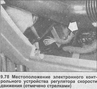
79. To access the block, open the glove box, then loosen and remove the five glove box mounting bolts. Remove the glove compartment from the panel, disconnecting the wiring connectors from the light and switch as they become accessible. Note that on models with air conditioning, it will also be necessary to disconnect the cold air hose at the back of the glove box.
80. Disconnect the wiring connector from the control unit, then unscrew the mounting screw and remove the unit through the glove box.
81. Installation is the reverse procedure of removal.
Control switches
82. The speed controller control switches are located at the end of the left lever of the steering column combination switch assembly. See Section 12 for removal and installation details.
Speed Regulator Relay
83 See Section 12, Chapter 16 (fig 12.6).
Power Window Components - Removal and Installation
84. Disconnect the negative battery terminal.
Window motor and regulator assembly
85 See Section 11, Chapter 20 for front doors and Section 11, Chapter 21 for rear doors.
Central console switches
86. Remove the central console as described in Section 11.
87. Press the mounting latches and remove the switch from the console.
88. Installation is the reverse procedure of removal.
Tailgate switches
89. Carefully remove the switch from the door trim panel with a lever and disconnect the electrical wiring connector.
90. Installation is the reverse procedure of removal.
Door lock control switch
91. See the information given for the central locking system in paragraphs 43 to 47 of this Chapter.
Windows with electric windows (models since 1988) - reprogramming
92. On 1988-on models, whenever the battery is disconnected, or if any of the power window components are removed, the power window control device must be reprogrammed as follows.
93. Close all doors, then turn on the ignition.
94. Close one of the windows by pressing the appropriate control switch until the window is completely closed.
With the window closed, hold down the switch for at least two seconds.
95. Repeat the procedure on the remaining window (nah).
Power door exterior mirror - removing and installing components
Mirror drive motor
96. Remove the mirror glass as described in Chapter 8 from this Section.
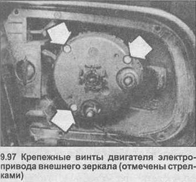
97. Unscrew the three mounting screws, then remove the motor from the mirror housing, disconnecting the electrical wiring connector as it becomes accessible (photo).
98. Installation is the reverse procedure of removal.
Mirror control switch
99. Remove the door trim panel as described in Section 11.
100. Press the retaining clips and remove the switch from the door panel.
101. Installation is the reverse procedure of removal.
Mirror heating time relay
102. On pre-1989 models, the mirror heating time relay is located behind the passenger panel (see fig. 12.6, insert «F», in Section 12). To remove the relay, remove the rear rubber trim and remove the trim panel. Disconnect the electrical wiring connector and pull the relay out of the mounting plate.
103. On models since 1989, the mirror heating time relay can be combined with (or instead) the rear window washer/wiper timing relay, which is located on the relay holder behind the fuse box. See Section 12, Chapter 16 for further information (and to Fig. 12.6, «H», relay no. 4).
Anti-theft alarm system - general description
104. Since 1990, an anti-theft alarm system has been fitted to all Sedan models as standard equipment and offered as an optional extra on most other models. At the time this book was written, very little information was available regarding the alarm system, so any problems with the system should be taken care of by the dealer.
105. Both the player and the graphic equalizer (where are used) can be withdrawn using the information given in Section 12, Chapter 40. Before disconnecting, mark the correct position of all wiring connectors.
Loudspeakers - removal and installation
Front door speakers
106 See Section 11, Chapter 13. Dashboard speakers
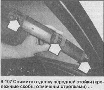
107. Carefully remove the trim panel from the appropriate A-pillar using a lever, noting that the trim panels are secured with three mounting brackets (photo).
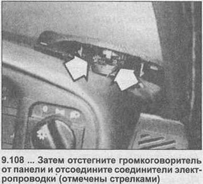
108. Remove the loudspeaker from the instrument panel with a lever, disconnecting the electrical wiring connectors as they become accessible (photo).
109. Installation is the reverse procedure of removal.
Rear Speakers - Sedan Models
110. Unfasten loudspeaker facing from the back panel.
111. Remove the four loudspeaker mounting screws, then lift the loudspeaker and disconnect the wiring connectors.
112. Installation is the reverse procedure of removal.
Rear Speakers - Estate Models
113 See Section 11, Chapter 10.
Antenna amplifier built into the windshield - removal and installation
114. On models with a windshield antenna, an amplifier is included in the antenna cable to boost the signal. The amplifier can be removed as follows.
115. Remove the right front speaker from the dashboard as described above.
116. Remove the radio or CD player as described in Section 12, noting also the information given in Section 105.
117. Trace the radio/CD player wiring back to the amplifier wiring connector, which is approximately 60mm from the main connector. Disconnect the amplifier.
118. Tie the end of the antenna cables to the radio with a piece of twine and disconnect the upper end of the wiring from the windshield.
119. Turn off a bolt of fastening, then get the amplifier through a loudspeaker slot. If the end of the antenna cable appears, untie the twine and leave it behind the panel; twine can be used during installation to pull the antenna cable and amplifier wiring connector into place through the radio opening.
120. Installation is the reverse procedure of removal.
Visitor comments