


Contents: MulTec central injection system ⬇ Bosch Motronic 1.5.5 injection system ⬇ Elements of the injection system…⬇
MulTec central injection system
The components included in the MulTec system are listed below in the accompanying illustration. In terms of operational efficiency, the system meets all requirements of international standards.
Main components and functional diagram of the MulTec injection system (1.2L OHC engine)
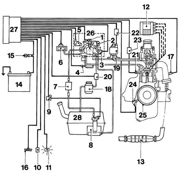
1 - Injector
2 — Fuel pressure regulator
3 — Stepper motor of the idle speed stabilization system
4 — Intake air temperature sensor (IAT)
5 — Throttle Position Potentiometer (TPS)
6 — Manifold Pressure (MAP) Sensor
7 — Fuel filter
8 — Fuel pump
9 — Fuel pump relay
10 — Frequency mileage sensor
11 — Malfunction Indicator Lamp (MIL)
12 — DIS ignition module
13 - Catalytic converter
14 — Battery
15 — Ignition switch
16 — Diagnostic connector
17 — Lambda probe
18 — EVAP fuel vapor canister
19 — EGR valve
20 — EVAP system check valve
21 — Knock sensor (KS)
22 — EGR control unit
23 — Knock control unit
24 — CKP sensor
25 — Crankshaft gear with CKP sensor rotor
26 — Throttle body
27 — Engine Control Module (ECM)
28 — Fuel tank
The fuel pump delivers fuel from the tank through the fuel filter to the throttle body or to the fuel rail.
The air-fuel mixture is injected into the throttle body via a central injector and enters the intake manifold, from where it is distributed to individual cylinders. The pressure regulator maintains the pressure in the intake manifold at a level 0.76 atm.
MulTec-M
There are 4 injectors connected to the fuel line. The pressure regulator maintains the fuel pressure in the line equal to 3.0 atm. The injectors are electronically controlled and inject fuel simultaneously into the intake manifold in front of the intake valves.
Air is sucked in by the engine through the air filter and the throttle valve pipe, by means of which the required amount of fuel is regulated. The vacuum in the intake manifold is registered by the corresponding sensor, as well as the temperature of the intake air. Based on these parameters, the control module determines the mass of the intake air. The intake air pressure sensor is located on the bulkhead of the engine compartment and is connected via a vacuum hose to the intake manifold.
The ECM regulates the required amount of fuel injected based on the intake air mass and other parameters such as engine temperature.
MulTec-S
From the fuel distribution line, fuel is supplied to the injectors. The pressure regulator in the line ensures that the pressure in it is maintained equal 3.0 atm. The injectors are controlled separately. The injection is performed in accordance with the ignition sequence, at the required moment.
On 1.6 l 109 hp engine. the intake air mass is measured by the MAF sensor. On other engines, the intake air mass is determined by the vacuum in the intake manifold. The mass determination is more accurate and faster. The ECM, based on the measured air mass and other parameters such as engine temperature, regulates the amount of fuel injected.
Bosch Motronic 1.5.5 injection system
In the accompanying illustrations the components of the injection system of DOHC 1.0 and 1.2 l engines are presented.
Bosch Motronic injection system components (DOHC engines 1.0 and 1.2 l)
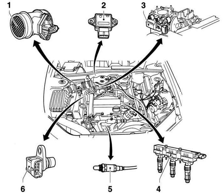
1 — MAF sensor
With backflow detection, i.e. the amount of fuel injected is calculated taking into account the volume of air expelled when the intake valves close. This ensures more accurate fuel delivery.
Additionally, an intake air temperature sensor is integrated into the air mass meter housing
2 — TPS
Provides information to the ECM about the current throttle position.
3 — Stepper motor for throttle valve
Based on the ECM signals, the stepper motor sets the throttle position and thus the idle speed
4 — Ignition module
The ignition module is placed on the spark plugs and secured to the cylinder head cover. Each spark plug has its own ignition coil, which is located directly above the built-in spark plug connector. There is no high-voltage wire
5 — Lambda probe
6 — CMP sensor
Bosch Motronic injection system components (DOHC engines 1.0 and 1.2 l)
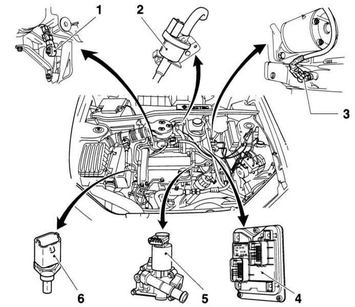
1 - Knock sensor
2 — EVAP Canister Purge Control Valve
3 — CKP sensor
4 — Engine control unit
Located directly at the engine or at the intake manifold. This ensures a minimum cable length. Has 2 connectors: for the engine and the instrument cluster
5 — EGR valve
It is located in the EGR housing and is controlled by the ECM and regulates the amount of exhaust gases returned to the engine. The EGR housing is fixed to the cylinder head and connects the exhaust manifold through a channel running in the cylinder head to the intake manifold. The EGR housing contains a coolant channel that goes to the heater.
Next to the EGR valve is the ECT sensor, which sends a signal to the indicator located on the instrument cluster
6 — ECT sensor
Transmits coolant temperature data to the ECM
Elements of the injection system (all engines)
The TPS is located directly on the throttle shaft and provides the ECM with information about the current throttle position.
The fuel pump relay is located in the footwell, behind the right A-pillar cover. The ECM is also located there. The relay controls power to the fuel pump and cuts power as soon as ignition pulses stop, such as if the engine stalls.
The CKP sensor is located on the side of the engine compartment and provides crankshaft speed information to the ECM.
The lambda probe measures the oxygen concentration in the exhaust gas flow and transmits the corresponding signals to the ECM. Based on the information received, the ECM changes the quality of the air-fuel mixture, which ensures optimal combustion of the exhaust gases in the catalytic converter.
The stepper motor of the idle speed control system regulates the idle speed, maintaining it constant, regardless of the use of additional units, such as power steering or crankcase ventilation. The electric motor is controlled by the ICM.
The EVAP system check valve is located on the engine compartment bulkhead. When the valve is open, fuel vapors from the canister are fed to the suction and burned in the engine.
The adsorber accumulates fuel vapors that form in the fuel tank due to temperature changes. The accumulated fuel vapors are then used and do not escape into the atmosphere.
The presence of detonation control ensures the engine 1.2 l and engines DOHC 1.4 and 1.6 l the ability to operate at the detonation limit and adapt to the quality of the fuel used. Detonation control allows the engine to operate at a high compression ratio. This in turn ensures the ability to optimally use fuel energy, which leads to a reduction in fuel consumption.
MAF sensor on engines 1.6 l (109 hp) is located at the outlet of the air filter. The MAF sensor housing contains a thin heated film, which is cooled by the air flowing around it. The control system regulates the heating current so that the film temperature (resistance controlled) remained constant. If, for example, as a result of increasing the throttle opening angle, more air is sucked in, the plate cools down. As a result, the heating current value increases so that the temperature remains constant. The current value corresponds to the mass of air sucked in.
CKP sensor in the system MULTEC-S serves to determine the cylinder for sequential injection. Thanks to this sensor, the ECM determines, for example, when the piston of cylinder 1 is at TDC.
On dOHC engines 1.4 and 1.6 l since 09.1994 the additional air mixing system corrects the composition of exhaust gases when the engine warms up.
Visitor comments