
Multec central injection system
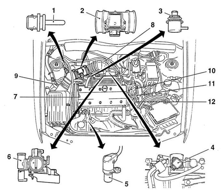
The main components of the Multec central injection system (1.6L SOHC engines)
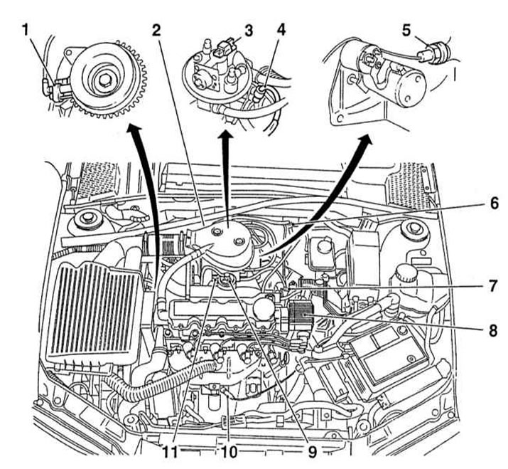
1 - Crankshaft position sensor (CKP)
2 - Throttle body
3 - Fuel injection injector
4 - Throttle position sensor (TPS)
5 - Knock sensor (KS)
6 - Absolute pressure sensor in the intake manifold (MAP)
7 — Valve of a purge of a coal adsorber
8 - Ignition module
9 - EGR valve
10 - Lambda probe
11 - Stepper motor of the idle speed stabilization system
Part of the Multitec system (see illustration The main components of the Multec central injection system (1.6L SOHC engines)) includes the following components: closed type catalytic converter, fuel vapor recovery systems (EVAP) and exhaust gas recirculation (EGR). In terms of the efficiency of functioning, the system meets all the requirements of international standards. Below is a description of the principle of operation of the engine part of the system responsible for fuel injection. Information on the functioning of the ignition subsystem is given in Chapter Engine electrical equipment.
A submersible fuel pump placed in the fuel tank provides fuel under pressure to the fuel line, driving it through a fuel filter mounted at the rear under the car along the way. The fuel supply pressure is determined by a pressure regulator mounted on the throttle body. Excess fuel is sent back to the fuel tank through the return line.
The electrical part of the control system consists of an electronic control module (ECM) and the following information sensors:
- Position sensor (potentiometer) throttle valve (TPS) informs the ECM of the throttle position;
- coolant temperature sensor (ECT) informs the ECM of the engine coolant temperature;
- Lambda probe (UK models) informs the ECM about the concentration of O 2 molecules in the exhaust gases (see more details. Systems of release and decrease in toxicity of the fulfilled gases);
- crankshaft position sensor (CKP) informs the ECM about engine speed and crankshaft position;
- Knock sensor (KS) informs the ECM of the appearance of signs of early ignition;
- Absolute pressure sensor in the intake manifold (MAP) informs the ECM about the load on the engine by monitoring the depth of depression in the intake manifold;
- Anti-lock brake control unit (ABS) informs the ECM about the speed of the vehicle;
- Air conditioning switch (with appropriate equipment) notifies the ECM that the A/C is on.
All incoming information is processed by the ECM, which then issues commands to control the ignition and open the fuel injection injector. The injector is controlled by changing the breadth of the control electrical opening pulse, which allows, with a minimum delay, to adjust the composition of the air-fuel mixture when external factors change. Thanks to the possibility of such adjustments, the engine output is maintained at the maximum level at any stage of the operation of the unit: at start-up, during warm-up, during acceleration, deceleration and movement at a constant speed.
The ECM also controls idle speed. The necessary adjustments are made by activating the stepper motor mounted on the throttle body. The engine, on commands from the ECM, opens / closes the bypass channel, if necessary (e.g. with the throttle closed or in the idle position) allowing air to bypass the throttle chamber.
In addition, the ECM controls the operation of the EVAP evaporative emission control system (see Systems of release and decrease in toxicity of the fulfilled gases).
If the sensors receive information indicating the occurrence of a non-emergency situation, the ECM switches to emergency operation mode, when the base values of the corresponding parameters are substituted for inadequate signals - the efficiency of the engine output in this mode naturally decreases. When the ECM enters the driver's emergency mode, the failure warning lamp on the vehicle's instrument panel warns (see chapter Manual), the corresponding diagnostic code is entered into the processor memory (see chapter Engine electrical equipment).
Under certain circumstances, the behavior of the car may not change at all. The only sign that the ECM has gone into emergency mode may be an increase in exhaust emissions. Keep in mind that after replacing a faulty sensor with a working one, the system will not automatically return to normal mode on its own - you should clear the processor memory of the diagnostic codes contained in it. Even if the reason for the transition of the system to the emergency safe mode was a broken wiring, after it the processor memory should be cleared.
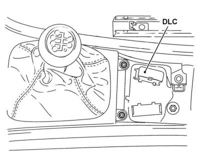
The DLC diagnostic connector is located in the center console in front of the parking brake lever under a decorative cover
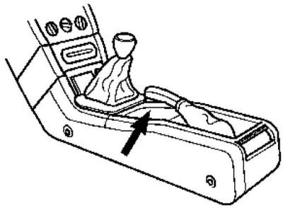
Location of the DLC connector in the console
Decorative cover removed
If the warning lamp comes on, the car should be driven to an Opel authorized service station as soon as possible for detailed diagnostics using special equipment and the necessary remedial repairs (see illustrations The DLC diagnostic connector is located in the center console in front of the parking brake lever under a decorative cover and Location of the DLC connector in the console).
Diagnostic equipment (scanner type reader) It is connected to the DLC connector located under the decorative trim under the front of the parking brake lever.
Multiport injection system Multec-S
Main components of the Multec-S central injection system (engines 1.4 and 1.6 l DOHC)
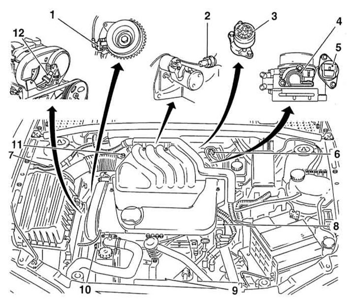
1 - Crankshaft position sensor (CKP)
2 - Knock sensor (KS)
3 - EGR valve
4 - Throttle position sensor (TPS)
5 - Stepper motor of the idle speed stabilization system
6 - Absolute pressure sensor in the intake manifold (MAP)
7 — Valve of a purge of a coal adsorber
8 - Ignition module
9 - Lambda probe
10 - Coolant temperature sensor (ECT)
11 - Intake air temperature sensor (IAT)
12 - Camshaft position sensor (CMP)
The main components of the Multec-S system (see illustration Main components of the Multec-S central injection system (engines 1.4 and 1.6 l DOHC)) are: closed type catalytic converter, fuel vapor recovery systems (EVAP) and exhaust gas recirculation (EGR). In terms of the efficiency of functioning, the system meets all the requirements of international standards. Below is a description of the principle of operation of the engine part of the system responsible for fuel injection. Information on the functioning of the ignition subsystem is given in Chapter Engine electrical equipment.
A submersible fuel pump placed in the fuel tank provides fuel under pressure to the fuel line, driving it through a fuel filter mounted at the rear under the car along the way. The fuel supply pressure is determined by a pressure regulator mounted on the throttle body. Excess fuel is sent back to the fuel tank through the return line.
The electrical part of the control system consists of an electronic control module (ECM) and the following information sensors:
- Position sensor (potentiometer) throttle valve (TPS) informs the ECM of the throttle position;
- coolant temperature sensor (ECT) informs the ECM of the engine coolant temperature;
- intake air temperature sensor (IAT) Informs the ECM about the temperature of the air sucked into the intake manifold;
- Lambda probe (UK models) informs the ECM about the concentration of O 2 molecules in the exhaust gases (see more details. Systems of release and decrease in toxicity of the fulfilled gases);
- crankshaft position sensor (CKP) informs the ECM about engine speed and crankshaft position;
- Camshaft position sensor (CMP) informs the ECM about the position and speed of the exhaust camshaft;
- Knock sensor (KS) informs the ECM of the appearance of signs of early ignition;
- Absolute pressure sensor in the intake manifold (MAP) informs the ECM about the load on the engine by monitoring the depth of depression in the intake manifold;
- Anti-lock brake control unit (ABS) informs the ECM about the speed of the vehicle;
- Air conditioning switch (with appropriate equipment) notifies the ECM that the A/C is on.
All incoming information is processed by the ECM, which then issues commands to control the ignition and open the fuel injection injector. The injector is controlled by changing the breadth of the control electrical opening pulse, which allows, with a minimum delay, to adjust the composition of the air-fuel mixture when external factors change. Thanks to the possibility of such adjustments, the engine output is maintained at the maximum level at any stage of the operation of the unit: at start-up, during warm-up, during acceleration, deceleration and movement at a constant speed. Multec S is a sequential injection system in which each of the 4 injection injectors fires at the start of opening of the corresponding intake valve.
The ECM also controls idle speed. The necessary adjustments are made by activating the stepper motor mounted on the throttle body. The engine, on commands from the ECM, opens / closes the bypass channel, if necessary (e.g. with the throttle closed or in the idle position) allowing air to bypass the throttle chamber.
In addition, the ECM controls the operation of the EVAP evaporative emission control system (see Systems of release and decrease in toxicity of the fulfilled gases).
If the sensors receive information indicating the occurrence of a non-emergency situation, the ECM switches to emergency operation, when the base values \u200b\u200bof the corresponding parameters are substituted for inadequate signals - the efficiency of the engine output in this mode naturally decreases. When the ECM enters the driver's emergency mode, the failure warning lamp on the vehicle's instrument panel warns (see chapter Manual), the corresponding diagnostic code is entered into the processor memory (see chapter Engine electrical equipment).
When the warning lamp comes on, the car should be driven to an Opel authorized service station as soon as possible for detailed diagnostics using special equipment and the necessary remedial repairs.
Diagnostic equipment (scanner type reader) connects to the DLC connector located under the decorative trim in front of the parking brake lever (see illustrations The DLC diagnostic connector is located in the center console in front of the parking brake lever under a decorative cover and Location of the DLC connector in the console).
Distributed injection system Simtec-70 h
Main components of the Multec-S central injection system (engines 1.8 and 2.0 l DOHC)
1 - Intake air temperature sensor (IAT)
2 - Air mass measurement sensor (MAF)
3 - Fuel pressure regulator
4 - Throttle position sensor (TPS)
5 - Crankshaft position sensor (CKP)
6 - Stepper motor of the idle speed stabilization system
7 - Camshaft position sensor (CMP)
8 - Knock sensor (KS)
9 - Purge valve of the coal adsorber
10 - Ignition module
11 - Coolant temperature sensor (ECT)
12 - EGR valve
According to the principle of operation of the Simtec-70 system (see illustration Main components of the Multec-S central injection system (engines 1.8 and 2.0 l DOHC)) almost identical to the Multec S system discussed above. The main difference is the use of an air mass sensor in the intake air path instead of the MAP sensor (MAF) film type inlet. Air mass sensor (MAF) informs the ECM about the amount of air entering the intake manifold.
Another feature of the system is the use of an inlet pipeline of variable length, which allows an increase in the torque developed by the engine at low speeds. The intake manifold is equipped with a special valve controlled by the ECM through a solenoid and diaphragm assembly. At engine speeds less than 3600 rpm, the valve remains closed - in this case, the air passes through a longer path, providing an increase in engine torque. At high speeds, the valve opens at the command of the ECM, providing a supply of pipeline vacuum to the diaphragm assembly, which controls the operation of four valves, the operation of which allows the length of the air path through the pipeline to be reduced to the required degree in order to increase the traction characteristics of the engine at high speeds.
Visitor comments