
See the warning at the beginning of the section Relieving pressure in the power supply system of gasoline engines.
Multec-S injection system
Before finally establishing your opinion about the failure of injectors, try adding any of the additives approved by car engine manufacturers to the fuel. Also make sure the fuel tank is clean.
1. Relieve the pressure in the supply system (see Relieving pressure in the power supply system of gasoline engines), then disconnect the negative cable from the battery.
2. Remove the oil filler cap, unscrew the fixing screws and remove the engine guard.
3. Disconnect the wiring from the intake air temperature sensor (IAT), disconnect the intake duct from the air cleaner and throttle body. On Zafira models, remove the sealing strip from the engine compartment and the fairing cover installed under the lower edge of the windshield. In order to provide access to the intake air duct, give the fixing nuts / bolts and remove the top cover of the front panel.
4. Disconnect the crankcase ventilation hoses from the timing cover.
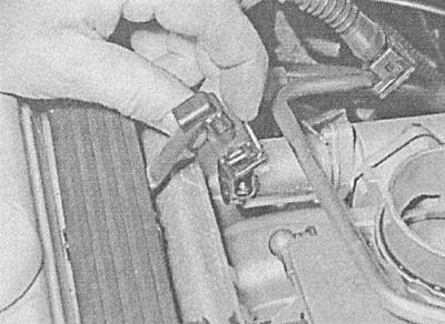
5. Disconnect all electrical wiring routed in the plastic route chute running along the fuel line - try to remember the order of laying the harnesses. The following components must be detached:
- Carbon adsorber purge valve;
- crankshaft position sensor (CKP);
- Emergency oil pressure sensor;
- Stepper motor of the idle speed stabilization system;
- coolant temperature sensor (ECT);
- Throttle position sensor (TPS);
- Camshaft position sensor (CMP);
- Absolute pressure sensor in the intake manifold (MAP);
- EGR valve;
- ignition module;
- Lambda probe;
- Upper ECM connector;
- Knock sensor (KS);
- Interference suppressor on the ignition module;
- Two pipeline grounding buses;
- Gray connector to the relay mounting block at the front of the engine compartment.
6. Disconnect a vacuum hose of a regulator of pressure of fuel in the left part of a fuel highway.
7. Disconnect the fuel lines from the fuel line - pay attention to the difference in the size of the union connections.
8. Turn out two fixing bolts and remove a fuel highway together with injectors and a plastic trench of an electroconducting.
9. If necessary, the injectors can be removed from the fuel line - release the corresponding clamps. The sealing rings of the injectors must be replaced without fail when installing the latter.
10. Installation is carried out in the reverse order. Pay attention to the following points:
- Lubricate new O-rings with a small amount of engine oil before installing.
- When filling injectors into the line, try to prevent displacement of the sealing rings. Track reliability of fixing of injectors.
- When installing the fuel line, take care not to damage the injectors. Tighten all fasteners to the required torque.
- Finally, start the engine and check the line for signs of leaks.
Fuel pressure control
1. Remove the oil filler cap, remove the fixing screws and remove the engine guard. Relieve system pressure (see Relieving pressure in the power supply system of gasoline engines) and disconnect the negative cable from the battery.
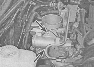
2. Disconnect the vacuum hose from the regulator.
3. Turn out the fixing screw and remove a regulator mounting collar.
4. Carefully release the regulator from the fuel line together with the sealing elements.
5. Installation is carried out in the reverse order. Don't forget to replace the sealing elements. Finally, start the engine and check the line for signs of leaks.
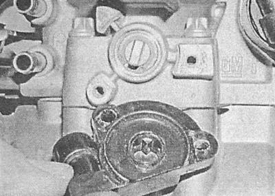
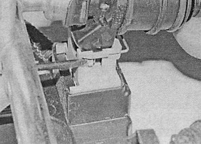
Stepping motor of the idle speed stabilization system
1. Remove the oil filler cap, remove the fixing screws and remove the engine guard.
2. Disconnect the wiring from the intake air temperature sensor (IAT), disconnect the intake duct from the air cleaner and throttle body. On Zafira models remove the sealing strip of the engine compartment and the fairing cover installed under the lower edge of the windshield. In order to provide access to the intake air duct, give the fixing nuts / bolts and remove the top cover of the front panel.
3. Disconnect the electrical wiring from the stepper motor.
4. Turn out two fixing screws and remove the electric motor from the throttle case.
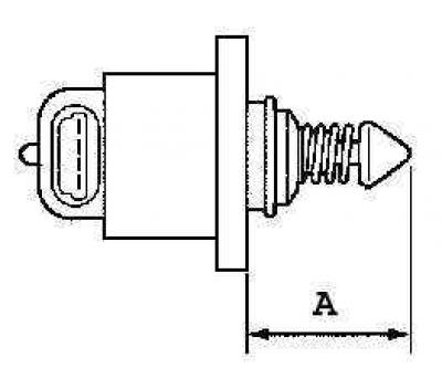
5. Installation is carried out in the reverse order. To check the proper functioning of the idle speed stabilization system, measure the amount of protrusion of the plunger (A) from the electric motor, - the result of the measurement should be no more than 33 mm, - if necessary, correct the position of the plunger. Lubricate the threaded part of the fixing screws with an anaerobic sealant before installation.
Throttle position sensor (TPS)
1. Remove the oil filler cap, remove the fixing screws and remove the engine guard.
2. Disconnect the wiring from the intake air temperature sensor (IAT), disconnect the intake duct from the air cleaner and throttle body. On Zafira models remove the sealing strip of the engine compartment and the fairing cover installed under the lower edge of the windshield. In order to provide access to the intake air duct, give the fixing nuts / bolts and remove the top cover of the front panel.
3. Make sure the ignition is off, then disconnect the wiring from the TPS sensor mounted on the throttle body.
4. Turn out fixing bolts and remove the gauge.
5. Installation is carried out in the reverse order. Check that the potentiometer is correctly engaged with the throttle shaft. Before screwing in the fixing bolts, grease their threaded part with an anaerobic sealant. After tightening the bolts to the required torque, connect the electrical wiring to the sensor.
6. Check the damper for proper operation, then reconnect the wiring and reinstall the intake duct.
Coolant temperature sensor (ECT)
The coolant temperature sensor is screwed into the thermostat housing. For instructions on how to remove and install the sensor, see Check of serviceability of functioning, removal and installation of electric components of a chain of management of the engine cooling system.
Intake air temperature sensor (IAT)
The sensor is installed in the intake duct connecting the air cleaner housing to the intake manifold.
1. Make sure that the ignition is off and disconnect the wiring from the sensor.
2. Using the utmost care, carefully remove the sensor assembly, being careful not to damage the air duct. Remove the sensor sealing element, which must be replaced.
3. Installation is carried out in the reverse order. Make sure that the sensor flange is properly aligned with the hole in the air intake duct.
Absolute pressure sensor in the pipeline (MAP)
The MAP sensor is mounted on the bulkhead of the engine compartment, to the left of the intake manifold.
1. Turn off the ignition, disconnect the electrical wiring and vacuum hose from the sensor. The sensor can now be removed from the bracket.
2. Installation is carried out in the reverse order.
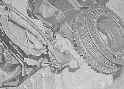
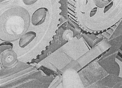
Crankshaft position sensor (CKP)
1. The sensor is installed on the right at the rear of the cylinder block and can be accessed from under the vehicle. Apply the parking brake, jack up the front of the vehicle and place it on jack stands. If equipped, remove the crankcase protection.
2. Walk along the electrical wiring from the sensor, releasing the harness from the intermediate clamps and remembering the route of its laying. Disconnect the connector - the sensor is removed together with part of the harness.
3. Turn out a fixing bolt and remove the gauge.
4. Installation is carried out in the reverse order. Make sure the fasteners are tightened to the correct torque. Make sure the gasket is correct and the harness is secure.
5. Finally, measure the distance between the sensor and the teeth of the sensor rotor on the crankshaft pulley - if the result exceeds 1.0±0.7mm, replace the sensor mounting bracket.
Camshaft position sensor (CMP)
1. Remove the top timing cover (see chapter Engine).
2. Walk along the electrical wiring from the sensor, releasing the harness from the intermediate clamps and remembering the route of its laying. Disconnect the connector.
3. Turn out fixing bolts and remove the gauge in gathering with electroconducting from a head of cylinders.
4. Installation is carried out in the reverse order. Lubricate the threaded part of the fixing bolts with an anaerobic sealant before screwing in. Tighten the bolts to the required torque. Follow the correct installation and reliability of fixing the electrical wiring.
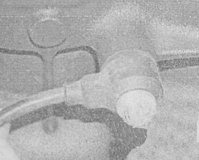
Knock sensor (KS)
The knock sensor is mounted on the rear wall of the cylinder block.
1. To gain access, apply the parking brake, jack up the vehicle and place it on jackstands. The sensor can be removed from below the vehicle.
2. Make sure that the ignition is off, then walk along the wiring from the sensor, releasing the harness from the intermediate clamps and remembering the route of its laying. Disconnect the connector.
3. Turn out a fixing bolt and remove the gauge.
4. Installation is carried out in the reverse order. Before installation, make sure that the mating surfaces are absolutely clean and dry. Tighten fasteners to the required torque. Check for correct wiring.
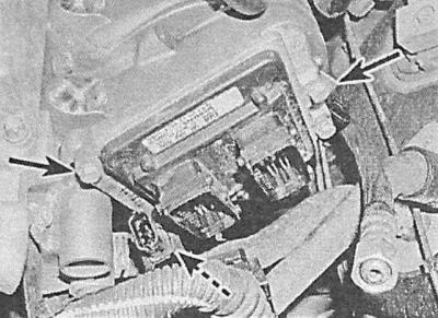
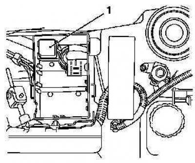
Electronic engine control module (ECM)
1. Disconnect the negative cable from the battery and open the cover of the relay mounting block located in the engine compartment.
2. Turn out two fixing screws, remove an oil filler cap and a protective casing of the engine.
3. Release clamps and disconnect from ECM electroconducting. Turn out three fixing bolts and remove the module.
4. Installation is carried out in the reverse order. Check that the electrical wiring is connected correctly.
When replacing the block, make its adaptation coding to the engine of your car in the Opel car service workshop.
Injection relay
The injection system relay is located in the mounting block located in the engine compartment.
1. Remove the cover from the mounting block. The system relay is colored magenta. Make sure the ignition is off, then release the relay from the block.

2. Installation is carried out in the reverse order.
Air conditioning switch
The sensor-switch of the air conditioning system is screwed into one of the lines of the refrigeration path and cannot be removed without first discharging the system (see chapter Cooling, heating systems). In view of the foregoing, the replacement of the sensor-switch should be carried out in the conditions of a car service workshop.
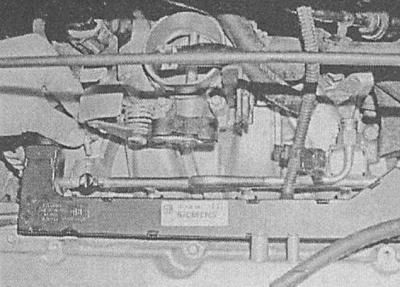
Simtec-70 injection system
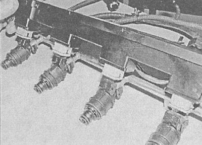
Fuel line with injection injectors
Before finally establishing your opinion about the failure of injectors, try adding any of the additives approved by car engine manufacturers to the fuel. Also make sure the fuel tank is clean.
1. Relieve the pressure in the supply system (see Relieving pressure in the power supply system of gasoline engines), then disconnect the negative cable from the battery.
2. Remove the oil filler cap, unscrew the fixing screws and remove the engine guard.
3. Disconnect the electrical wiring from the air mass sensor (MAF), disconnect the intake duct from the air cleaner and throttle body. On Zafira models, remove the sealing strip from the engine compartment and the fairing cover installed under the lower edge of the windshield. In order to provide access to the intake air duct, give the fixing nuts / bolts and remove the top cover of the front panel.
4. Disconnect the crankcase ventilation hoses from the timing cover and throttle body.
5. Disconnect all electrical wiring routed in the plastic route chute running along the fuel line - try to remember the order of laying the harnesses. Release the tourniquet from the chute.
6. Turn out fixing bolts and disconnect tires of grounding from a trench of an electroconducting to the right of the inlet pipeline and ECM to the left of the pipeline.
7. Turn out a bolt of fastening of a trench.
8. Disconnect the fuel lines from the fuel line - pay attention to the difference in the size of the union connections.
9. Turn out two fixing bolts and remove a fuel highway together with injectors and a plastic trench of an electroconducting. Remove and discard the lower o-rings - they must be replaced on reassembly without fail.
10. Release the latches and carefully remove the electrical wiring chute from the injectors - the connectors are built into the chute and cannot be replaced individually.
11. Release the corresponding clamps and remove the injectors from the fuel line. Remove the upper sealing rings; when installing the ring, it must be replaced without fail.
12. Installation is carried out in the reverse order. Pay attention to the following points:
- Lubricate new O-rings with a small amount of engine oil before installing.
- When filling injectors into the line, try to prevent displacement of the sealing rings. Track reliability of fixing of injectors.
- When installing the fuel line, take care not to damage the injectors. Tighten all fasteners to the required torque.
- When installing the gutter, make sure that the connectors of the injectors are connected correctly.
- Finally, start the engine and check the line for signs of leaks.
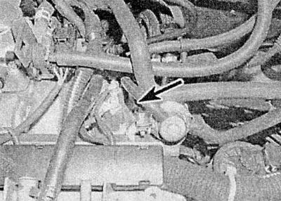
Fuel pressure control
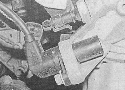
1. On models 1.8 l the fuel pressure is regulated by the fuel pump module placed in the fuel tank, - the regulator is installed under the pump cover, it is not supplied to the spare parts markets individually and in case of failure the entire pump assembly must be replaced (For a description of the removal and installation procedures for the pump assembly, see Removal and installation of the fuel pump - petrol models). Disconnect the fuel lines from the regulator, disconnect the electrical wiring, disconnect the electrical wiring under the pump cover. On engines 2.0 l remove the engine cover. Relieve pressure in the supply system (see Relieving pressure in the power supply system of gasoline engines) and disconnect the negative cable from the battery.
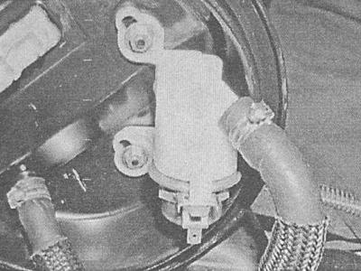
2. Disconnect the vacuum hose from the regulator (1).
3. Turn out the fixing screw and remove the mounting collar (2) regulator.
4. Carefully release the regulator from the fuel line together with the sealing elements.
5. Installation is carried out in the reverse order. Don't forget to replace the sealing elements. Finally, start the engine and check the line for signs of leaks.
Throttle Control - 1.8L Models
On models 1.8 l engine speed is controlled by the ECM using the throttle control. Position sensor (potentiometer) throttle valve (TPS) built into the regulator, which is an integral part of the throttle body. In the event of a malfunction in the functioning of any of the elements, the throttle body must be replaced as an assembly (see Removal and installation of the throttle body - petrol models).
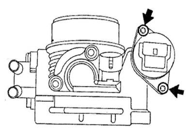
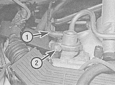
Idle Stabilization Stepper Motor - 2.0L Models
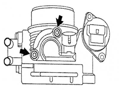
1. Disconnect the wiring from the air mass sensor (MAF). Loosen the clamp and disconnect the crankcase ventilation hose from the rear of the timing cover, then disconnect the air intake duct. On Zafira models remove the sealing strip of the engine compartment and the fairing cover installed under the lower edge of the windshield. In order to provide access to the intake air duct, give the fixing nuts / bolts and remove the top cover of the front panel.
2. Disconnect the wiring from the stepper motor.
3. Remove the two fixing screws and remove the electric motor from the throttle body - the sealing gasket must be replaced without fail.
A - Disconnecting the stepper motor wiring connector
B - Stepper Motor Mounting Screws
A.
B.
4. Installation is carried out in the reverse order. Don't forget to replace the gasket. Tighten all fasteners to the required torque.
Position sensor (potentiometer) throttle valve (TPS)
1. On engines 1.8 l The sensor is built into the throttle control. On engines 2.0 l remove throttle body (see Removal and installation of the throttle body - petrol models).
2. Turn out fixing bolts and remove the gauge from the throttle body.
3. Installation is carried out in the reverse order. Check that the potentiometer is correctly engaged with the throttle shaft.
Coolant temperature sensor (ECT)
The coolant temperature sensor is screwed into the rear of the intake manifold. For instructions on how to remove and install the sensor, see Check of serviceability of functioning, removal and installation of electric components of a chain of management of the engine cooling system.
Intake air temperature sensor (IAT)
The functions of the IAT sensor are performed by the air mass sensor (MAF), - see below.
Air Mass Sensor (MAF)
1. Turn off the ignition and disconnect the wiring from the sensor.
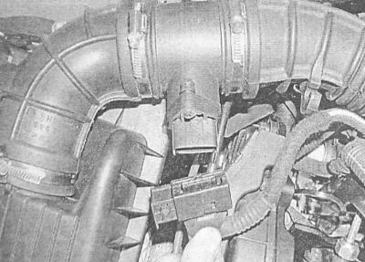
2. Release fixing collars, disconnect inlet air lines and remove the gauge from the engine. On Zafira models remove the sealing strip of the engine compartment and the fairing cover installed under the lower edge of the windshield. In order to provide access to the intake air duct, give the fixing nuts / bolts and remove the top cover of the front panel.
3. Installation is carried out in the reverse order. Check that the air ducts are connected correctly.
Crankshaft position sensor (CKP) - 1.8 l models
1. The sensor is mounted on a bracket on the right at the rear of the cylinder block, it can be accessed from under the car. To gain access, apply the parking brake, jack up the front of the vehicle and support it on jack stands and remove the crankcase.
2. Walk away from the sensor along the wiring harness, releasing it from the intermediate clamps. Disconnect the connector - the sensor is removed together with a piece of wiring mounted in it.
3. Turn out a fixing bolt and remove the gauge from the block of cylinders.
4. Installation is carried out in the reverse order. Tighten the sensor mounting bolt to the required torque. Follow the correct laying and reliability of fixing the wiring.
Crankshaft position sensor (CKP) - 2.0 l models
1. Remove the air cleaner (see Removal and installation of components of an inlet air path).
2. On equipped with A/C models unscrew the mounting bolt and remove the dipstick guide tube from the front of the cylinder block.
3. Walk away from the sensor along the wiring harness, releasing it from the intermediate clamps. Disconnect the connector - the sensor is removed together with a piece of wiring mounted in it.
4. Turn out a fixing bolt and remove the gauge from the block of cylinders, - a sealing ring is subject to replacement without fail.
5. Installation is carried out in the reverse order. Do not forget to replace the sealing ring, tighten the sensor mounting bolt with the required force. Follow the correct laying and reliability of fixing the wiring.
Camshaft position sensor (CMP)
1. On engines 1.8 l remove the oil filler cap, unscrew the fixing screws and remove the engine protection cover. On engines 2.0 l Remove the mounting screws and remove the spark plug cover from the top of the cylinder head.
2. Turn off the ignition and disconnect the wiring from the sensor.
3. Remove the top timing cover (see chapter Engine).
4. Turn out fixing bolts and remove the gauge from a head of cylinders.
5. Installation is carried out in the reverse order. Lubricate the threaded part of the fixing bolts with an anaerobic sealant before screwing in. Tighten the bolts to the required torque.
Knock sensor (KS)
1. The knock sensor is installed on the rear wall of the cylinder block. Apply the parking brake, jack up the vehicle and support it on jack stands to gain access. The sensor can be removed from below the vehicle.
2. On engines 2.0 l remove the starter (see chapter Engine electrical equipment).
3. Make sure the ignition is off, then walk along the wiring from the sensor, releasing the harness from the intermediate clamps and remembering the route of its laying. Disconnect the connector.
4. Turn out a fixing bolt and remove the gauge.
5. Installation is carried out in the reverse order. Before installation, make sure that the mating surfaces are absolutely clean and dry. Tighten fasteners to the required torque. Check for correct wiring. On engines 2.0 l install the starter (see chapter Engine electrical equipment).
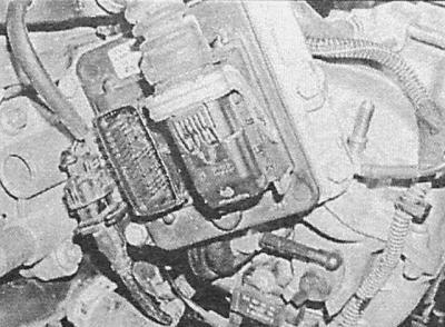
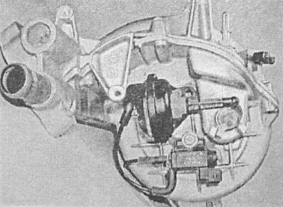
Electronic engine control module (ECM)
ECM mount on 2.0L models
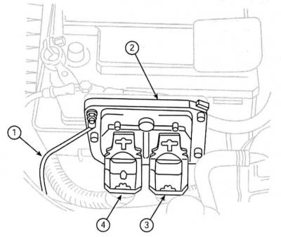
1 - Ground bus
2 - Control module (ECM)
3 — the Contact socket of an electrical wiring
4 — the Contact socket of an electroconducting
1. Disconnect the negative cable from the battery. Open the cover of the relay mounting block located in the engine compartment.
2. On engines 1.8 l The ECM is bolted to the left side of the intake manifold. On engines 2.0 l the module is mounted behind the battery.
3. Release clamps and disconnect from ECM electroconducting. Disconnect the ground bar from the module frame. On engines 1.8 l, without disconnecting, release the electrical wiring connector from the support bracket on the ECM frame.
4. Remove the three mounting bolts and remove the ECM from the vehicle, note that the lower module mounting bolt is also used to attach the electrical wiring connector support bracket (see illustration ECM mount on 2.0L models).
5. Installation is carried out in the reverse order. Check that the electrical wiring is connected correctly.
When replacing the block, make its adaptation coding to the engine of your car in the Opel car service workshop.
Injection relay
The injection system relay is located in the mounting block located in the engine compartment.
1. Remove the cover from the mounting block. The system relay is colored magenta. Make sure the ignition is off, then release the relay from the block.
2. Installation is carried out in the reverse order.
Air conditioning switch
The sensor-switch of the air conditioning system is screwed into one of the lines of the refrigeration path, and cannot be removed without first discharging the system (see chapter Cooling, heating systems). In view of the foregoing, the replacement of the sensor-switch should be carried out in the conditions of a car service workshop.
Function control solenoid inlet manifold changeover valve
The solenoid for controlling the operation of the pipeline switching valve is installed on the left side of the latter.
1. Turn off the ignition and disconnect the wiring from the valve.
2. Disconnect both vacuum hoses, turn out the fixing screw and remove an electromagnet.
3. Installation is carried out in the reverse order.
Diaphragm assembly for controlling the operation of the intake manifold switching valve
The diaphragm assembly is installed on the left side of the intake manifold.
1. On engines 1.8 l remove the ECM (see above). On engines 2.0 l remove the intake manifold (see Removal and installation of the inlet pipeline).
2. On engines 1.8 l disconnect the vacuum hose, disconnect the diaphragm rod from the hinge, unscrew the fixing bolts and remove the diaphragm assembly from the pipeline. On engines 2.0 l unscrew the nut that secures the diaphragm stem to the valve lever, remove the pin that secures the diaphragm housing to the intake manifold and disconnect the vacuum hose.
3. Installation is carried out in the reverse order.
Visitor comments