


SOHC engines
New pipeline fastening nuts are required during installation.
1. Relieve the pressure in the fuel system (see Relieving pressure in the fuel system of gasoline engines). Disconnect the negative cable from the battery.
2. Remove the accessory drive belt and drain the cooling system (see Chapter Routine maintenance).
3. Remove the air cleaner and air intake ducts (see Removal and installation air intake tract components).
4. Disconnect the vacuum hoses and crankcase ventilation hoses from the throttle body cover, unscrew the mounting screws and remove the cover with the sealing ring from the throttle body.
5. Disconnect the wiring harness from the TPS sensor, idle speed control stepper motor, fuel injector, ECT sensor, EGR valve, fuel tank vent valve, and MAP sensor. Release the wiring harnesses from the intermediate retainers - try to remember the order in which they are installed. Remove the wiring harness routing channel from the camshaft cover and move it away from the intake manifold.
6. Remove the bolts securing the generator mounting bracket to the intake manifold. Release the generator from the eye and tilt it back.
7. Loosen the union nuts and disconnect the fuel hoses from the throttle body. When loosening the nuts, hold the connector from turning using a second open-end wrench.
8. Disconnect the drive rod from the throttle shaft, unscrew the two mounting bolts and remove the support bracket from the pipeline together with the cable sheath secured in it.
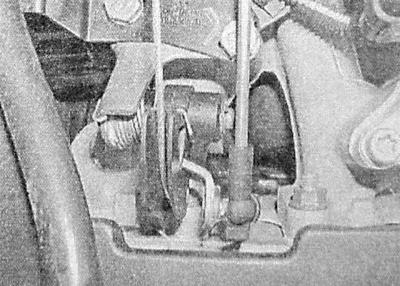
9. Disconnect the vacuum hoses and crankcase ventilation hoses from the throttle body, try to remember the installation position of the components. Disconnect the vacuum hose from the fuel tank ventilation valve.
10. Loosen the clamp and disconnect the coolant hose from the rear of the intake manifold.
11. Release the clamp and remove the brake booster servo hose from the pipeline.
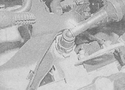
12. Make sure that all communication lines are disconnected and nothing interferes with the removal of the pipeline. Unscrew the pipeline fastening nuts.
13. Remove the pipeline from the engine and remove the sealing gasket from it - try to remember the installation position of the gasket.
14. Installation is carried out in reverse order. Please note the following points:
- Before installation, check the condition of the pipeline fastening studs - replace defective studs. Use new pipeline fastening nuts;
- Before installation, make sure that the mating surfaces of the pipeline and the unit are absolutely clean and dry, do not forget to replace the sealing gasket. Tighten the fastening nuts with the required force in several steps - try to ensure complete uniformity;
- Ensure that all communication lines are connected correctly and securely fastened;
- Make sure the fuel line union nuts and brake booster hose are tightened to the specified torque.
15. Finally, install the accessory drive belt and fill the cooling system (see Chapter Routine maintenance).
Engines 1.4 and 1.6 l DOHC
If only the rear portion of the pipe is to be removed, follow the procedures in paragraphs 1 through 15.
1. Remove the oil filler cap, unscrew the fastening screws and remove the engine protective cover. Screw the oil filler cap back into place. Drain the cooling system (see Chapter Routine maintenance).
2. Remove the air cleaner with the intake duct (see Removal and installation air intake tract components).
3. Overcoming the resistance of the spring, turn the tensioner by the central bolt and remove the accessory drive belt from the pulleys.
4. Loosen the mounting bolts and remove the generator support bracket from the right side of the pipeline.
5. Loosen the lower generator mounting bolt and tilt the generator back.
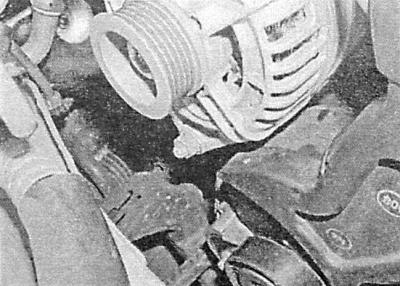
6. Remove the support bracket installed between the intake manifold and the cylinder block.
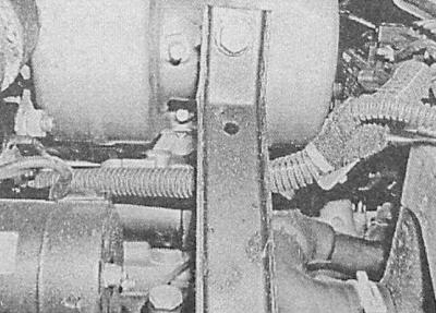
7. Disconnect the crankcase ventilation hose from the timing cover.
8. Remove the fuel line with the injection injectors (see Removal and installation of components of distributed fuel injection systems Multec-S and Simtec-70).
9. Disconnect the throttle cable from the throttle body and release it from the support bracket (see Removal, installation and adjusting the throttle cable - petrol models).
10. Disconnect the wiring from the idle speed control stepper motor and the TPS sensor.
11. Loosen the mounting clamp and disconnect the brake booster servo hose from the pipeline.
12. Disconnect the vacuum hose from the MAP sensor.
13. Disconnect the fuel tank ventilation hose from the throttle body.
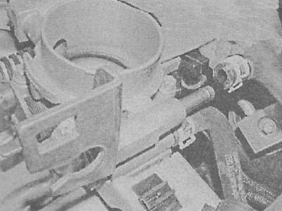
14. Loosen the clamps and disconnect the cooling system hoses from the throttle body.
15. Unscrew the fastening bolts and remove the pipeline from the mounting flange. It is not recommended to disassemble the pipeline.
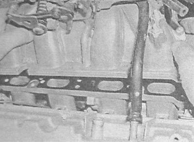
16. To remove the mounting flange, disconnect the cooling tract hose from its left part.
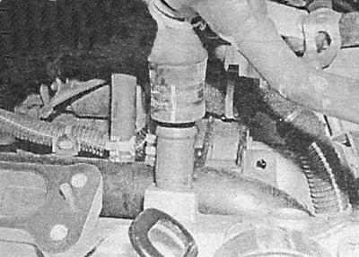
17. Unscrew the fastening nuts and remove the flange from the cylinder head - to remove the flange from the studs, you will have to press the cooling tract hose down a little.
18. Installation is carried out in reverse order. Please note the following points:
- Before installation, check the condition of the pipeline mounting studs - replace damaged elements;
- Before installation, make sure that the mating surfaces are absolutely clean and dry, do not forget to replace the sealing gasket. If you removed the flange, make sure that the nuts that secure it are tightened evenly and with the required force;
- Install the rear part of the manifold, do not forget to replace the gasket. Make sure that the mounting bolts are tightened to the required torque;
- Restore the original connection of all communication lines - ensure that they are connected correctly and securely fastened;
- Make sure that the nuts of the nipple connections are tightened to the required force;
19. Finally, fill the cooling system (see Chapter Routine maintenance) and adjusting the throttle cable (see Removal, installation and adjusting the throttle cable - petrol models).
Engines 1.8 and 2.0 l
New pipeline fastening nuts are required during installation.
1. Remove the accessory drive belt and drain the cooling system (see Chapter Routine maintenance).
2. Relieve the pressure in the fuel system (see Relieving pressure in the fuel system of gasoline engines). Disconnect the negative cable from the battery.
3. Remove the oil filler cap, unscrew the mounting screws and remove the engine protective cover.
4. Disconnect the wiring from the MAF sensor.
5. Loosen the mounting clamps, disconnect the intake air duct assembly with the MAF sensor zafira models remove the engine compartment sealing strip and the cowl cover located under the lower edge of the windshield. To gain access to the air intake duct, loosen the mounting nuts/bolts and remove the upper front panel cover.
6. Release the lock and disconnect the gas cable from the hinge, release the cable from the support bracket.
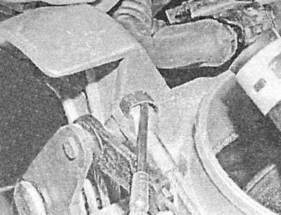
On models equipped with an engine management system, remove the cruise control drive cable - the cable is attached to the hinge with a spring clip.
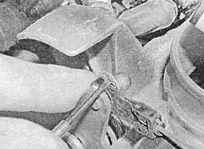
7. Loosen the clamps and disconnect the crankcase ventilation hoses from the camshaft cover and throttle body.
8. Disconnect the cooling system hoses from the throttle body. Disconnect the cooling system pipe from the valve cover and the left edge of the intake manifold and move it to the side.
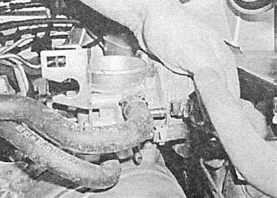
9. Disconnect the fuel tank ventilation hose from the throttle body.
10. On 2.0L engines disconnect the wiring from the TPS sensor and the idle speed control valve 1.8 l engines disconnect the wiring from the throttle control valve.
11. Disconnect all remaining hoses from the throttle body - try to remember the installation position of the components.
12. On 1.8 l engines loosen the lower generator mounting bolt and remove the upper mounting bolt. Remove the mounting bolts and separate the generator support bracket from the intake manifold and cylinder head. On 2.0L engines remove the generator support bracket from the intake manifold, also remove the generator mounting bracket to the cooling system flange and intake manifold. Tilt the generator back.
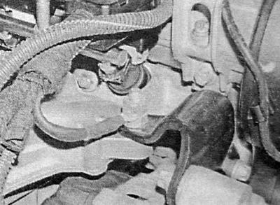
13. Loosen the mounting bolts and remove the support bracket from the base of the pipeline.
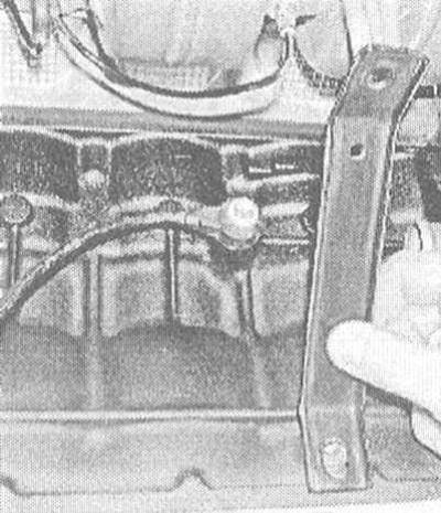
14. On 1.8 l engines loosen the union nut and disconnect the fuel line from the fuel line - when releasing the union nut, hold the connector from turning with a second key 2.0L engines disconnect the return fuel line from the pressure regulator, disconnect the fuel supply line from the fuel line.
15. Disconnect the wiring from the crankshaft position (CKP) sensor and the intake manifold switching solenoid valve, and also disconnect the contact connectors of all the harnesses laid in the routing chute installed above the injection injectors. Unscrew the left mounting bolt of the chute 2.0L engines remove the spark plug cover and disconnect the wiring from the camshaft position (CMP) sensor.
16. Unscrew the bolts securing the fuel line to the intake manifold, remove the line assembly with the injectors and the wiring channel.
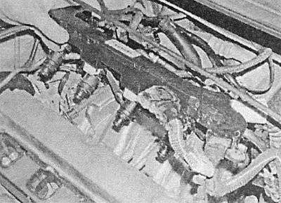
17. Disconnect the brake booster servo hose from the intake manifold. Disconnect any remaining vacuum/air hoses from the manifold - try to remember the installation positions of the components.
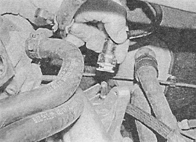
18. Disconnect the heater hose from the intake manifold.
19. Loosen the mounting bolts and remove the rear engine transport eye from the cylinder head.
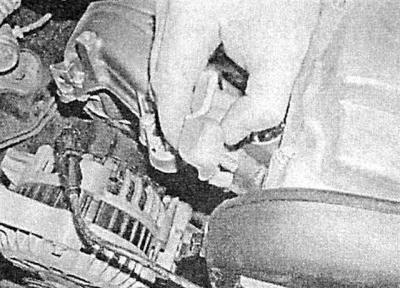
20. Remove the TORX head screws (1.8L engines) and nuts (2.0L engines), and remove the throttle body from the intake manifold.
21. On 2.0L models equipped with manual transmission release the connector and disconnect the tube from the clutch hydraulic cylinder 1.8 l engines disconnect the remaining wiring, remove the three mounting bolts and remove the ECM from the intake manifold.
22. Remove the mounting bolts/nuts and remove the pipe from the engine.
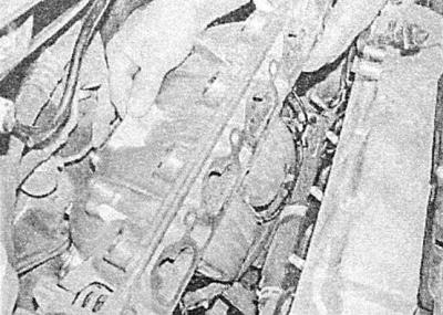
23. Remove and discard the sealing gasket.
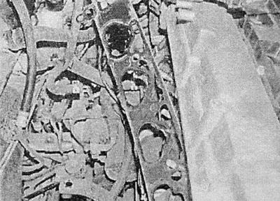
Do not attempt to disassemble the intake manifold - only the diaphragm and electromagnetic valve units are supplied individually to the aftermarket.
24. Installation is carried out in reverse order.
Original source is on the website www.OPELBOOK.ru
- Before installation, check the condition of the pipeline mounting studs - replace damaged elements;
- Before installation, make sure that the mating surfaces are absolutely clean and dry, do not forget to replace the sealing gasket. Make sure that the mounting bolts are tightened with the required force;
- Restore the original connection of all communication lines - ensure that they are connected correctly and securely fastened;
- On models with manual transmission, check the proper functioning of the clutch, if necessary, bleed the hydraulic circuit (see Chapter Clutch and drive shafts).
- Make sure that the nuts of the union connections are tightened to the required torque.
25. Finally, install the accessory drive belt and fill the cooling system (see Chapter Routine maintenance) and adjusting the throttle cable (see Removal, installation and adjusting the throttle cable - petrol models).
Visitor comments