
Removing
Petrol models
Astra models
1. Loosen the clamp securing the intake duct to the throttle body. Release the latches securing the air duct to the air cleaner housing, give the fixing screw / nut (And) and remove the air cleaner assembly from the engine compartment.
2. Release the carbon canister purge valve from the bracket on the air cleaner housing.
On models with central injection, you will also need to disconnect the vacuum hose and the warm air supply hose from the air cleaner housing.
3. In some cases, the dismantling of the air cleaner is associated with the disconnection of the hoses of the crankcase ventilation system and the disconnection of the electrical wiring connectors. Sometimes the air duct is attracted to the bracket with bolts.

Models Zafira
1. Remove the sealing strip of the engine compartment and the fairing cover installed under the lower edge of the windshield.
2. In order to provide access to the intake air duct, give the fixing nuts / bolts and remove the top cover of the front panel.
3. Remove the air cleaner and air ducts (see above).
Diesel models
Models 1.7 l
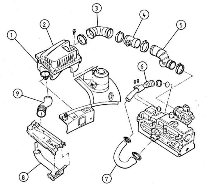
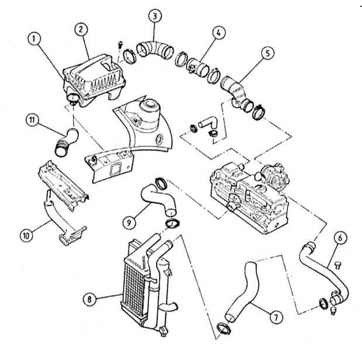
Scheme of connection of the components of the intake air path (1.7L SOHC models)
1 - Air cleaner housing cover
2 - Inlet air duct
3 - Air mass measurement sensor (MAF)
4 - Inlet air duct
5 - Turbocharger
6 - Boost sleeve
7 - boost hose
8 - Intercooler
9 - Inlet air duct
10 - Connecting sleeve
11 - Air cleaner housing
Scheme of connection of the components of the intake air path (1.7L DOHC models)
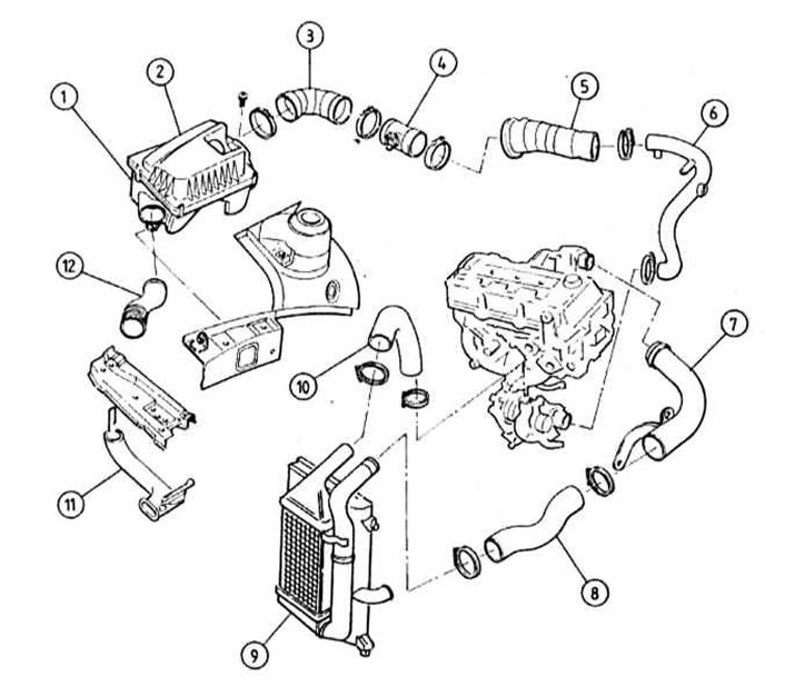
1 - Air cleaner housing
2 — Cover of the case of an air cleaner
3 - Intake air duct
4 - Air mass measurement sensor (MAF)
5 - Inlet air duct
6 — the Inlet pipeline
7 - Inlet tube boost
8 - Connecting hose
9 - Intercooler
10 - boost hose
11 - Boost sleeve
12 - Connecting sleeve
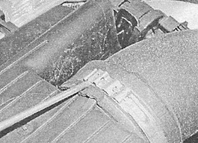
1. Loosen the clamp and remove the intake duct from the back of the air cleaner housing (see illustrations Scheme of connection of the components of the intake air path (1.7L SOHC models) and Scheme of connection of the components of the intake air path (1.7L DOHC models)).
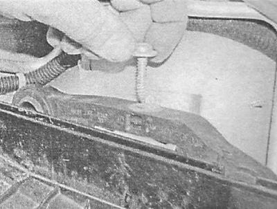
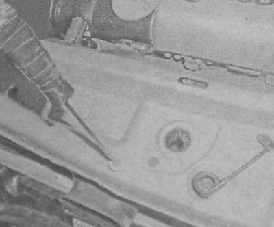
2. Remove the screws (with TORX sockets) fastening the air cleaner bracket to the body and remove the air cleaner from the engine, - note that there is a protrusion in the lower part of the air cleaner housing, which, when installed, must be correctly aligned with the reciprocal recess in the mudguard.
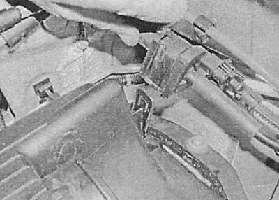
3. Other air ducts leading to the turbocharger, intercooler and intake manifold can be removed by loosening the corresponding clamps and removing the fixing screws. Please note that an air mass sensor is mounted in the air duct connecting the air cleaner housing and the intake jack (MAF), - Before removing the intake duct, disconnect the electrical wiring and remove the sensor.
Models 2.0 l
Scheme of connection of the components of the intake air path (2.0L low pressure turbo models)
1 - Air cleaner housing
2 — Cover of the case of an air cleaner
3 - Inlet air duct
4 - MAF sensor
5 - Inlet air duct
6 - Boost sleeve
7 - Connecting hose
8 - Inlet air duct
9 - Connecting sleeve
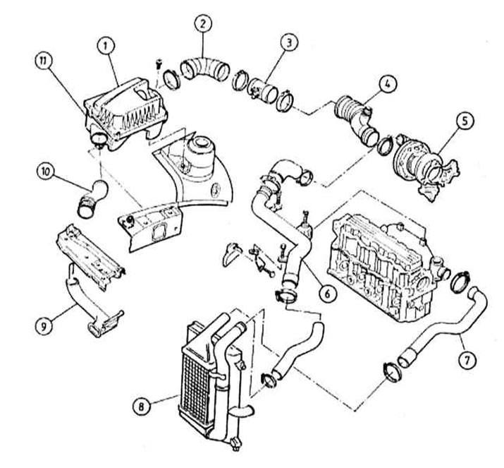
Scheme of connection of the components of the intake air path (2.0L models with high-pressure turbocharging)
1 - Air cleaner housing
2 — Cover of the case of an air cleaner
3 - Inlet air duct
4 - MAF sensor
5 - Inlet air duct
6 - Boost sleeve
7 - boost hose
8 - Intercooler
9 - boost hose
10 - Inlet air duct
11 - Connecting sleeve
1. On Zafira models, remove the sealing strip from the engine compartment and the fairing cover installed under the lower edge of the windshield. In order to provide access to the intake air duct, give the fixing nuts / bolts and remove the top cover of the front panel.
2. On all models, disconnect the negative cable from the battery, as well as the wiring from the MAF sensors and, if installed, the intake air temperature (IAT).
3. Disconnect the crankcase ventilation hose from the intake air duct, loosen the fastening clamp and remove the air duct assembly together with the air mass meter sensor and remove it from under the hood.
4. Release the latches, remove the cover of the air cleaner housing and remove the filter element - try to remember the installation position of the components. Turn out a fixing bolt and remove the case of an air cleaner, having disconnected it from an inlet air duct.
5. On low pressure turbo models (motors X20DTL/Y20DTL) (see illustration Scheme of connection of the components of the intake air path (2.0L low pressure turbo models)) to remove the air ducts leading to the turbocharger and intake manifold, first unscrew the fixing screws and remove the plastic protective cover from the engine. Release the latch on the air duct that connects the metal sleeve to the pipeline. Turn out bolts of fastening of a tube to a cover of a head of cylinders, loosen a fixing collar and disconnect a sleeve from a turbocharger. Remove the hose/duct assembly from the top of the engine and remove the o-ring installed between the hose and the compressor.
6. On models with high-pressure turbocharging (Y2ODTH engine) (see illustration Scheme of connection of the components of the intake air path (2.0L models with high-pressure turbocharging)) release the fixing clamps / give the bolts and remove the air ducts connecting the intercooler and the inlet pipeline, as well as the turbocharger sleeve. To remove the metal sleeve, disconnect the air duct from it, then loosen the clamp securing the sleeve to the turbocharger. Turn out a fixing bolt and remove a sleeve from the engine, - pay attention to the sealing ring installed.
Installation
All models
Installation is carried out in the reverse order to the dismantling of the components.
1. Track reliability of a tightening of collars of fastening of air ducts. On diesel engines 2.0 l do not forget to replace the sealing ring at the junction of the metal sleeve with the turbocharger (if the sleeve was disconnected).
Visitor comments