


Removal
1. The general connection diagram of the air supply system intake tract components is shown in the accompanying illustrations. Basically, the fastening of pipelines and hoses is carried out using clamps of various types. In some cases, bolted connections are used for this purpose.
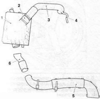
6.1a Air intake tract (using the Z18XE engine as an example): 1. Air purifier; 2. Air mass measurement sensor; 3. Air intake duct; 4. Crankcase ventilation hose; 5. Front air intake duct; 6. Connecting sleeve
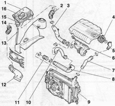
6.1b Schematic diagram of the connection of the components of the intake air tract of a turbocharged engine (using the Z19DTH engine as an example): 1. Air cleaner housing; 2. Air intake duct; 3. Boost sleeve; 4. Throttle body pipe; 5, 7, 10, 11. Boost hoses; 6. Turbocharger with exhaust manifold; 8. Boost pipe; 9. Charge air cooler (intercooler); 12. Resonator; 13. Drainage tube; 14. Connecting sleeve; 15. Lower part of the air filter housing; 16. Air mass measurement sensor
2. The most important element of the air supply system is the air cleaner. When performing maintenance work, it is enough to remove only the top cover, but when performing many repairs and replacing other elements of the engine compartment, it is necessary to dismantle the entire air cleaner assembly.
3. This Section provides a detailed description of the procedure for removing the air cleaner on the Z18XE engine. On other engines, this operation is performed in a similar manner.
4. After pressing the lock, disconnect the air mass sensor wiring connector. Release the wiring harness by cutting the holders, if necessary, mark their position for subsequent installation of new ones.
5. Disconnect the hose (see illustration 6.1a) crankcase ventilation system, loosen the mounting clamps and remove the intake manifold. Release the air cleaner from the holders, disconnect the connecting hose and remove the air cleaner housing from the engine compartment
6. On Y20DTH/Y22DTR engines, when removing the air cleaner, additionally pull the holder upwards (see accompanying illustration) electromagnetic valve and atmospheric pressure sensor.
(Material copied from this website: «www.opelbook.ru»)
Visitor comments