
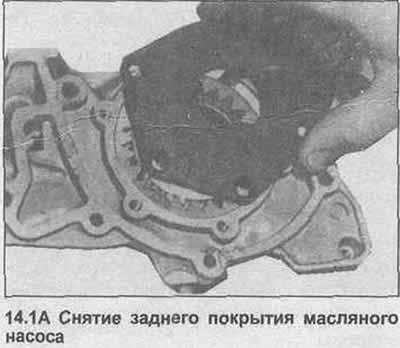
Oil pump
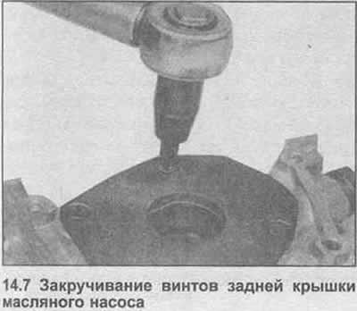
1. Remove the connecting rod head screws, remove the back cover (photo).
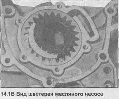
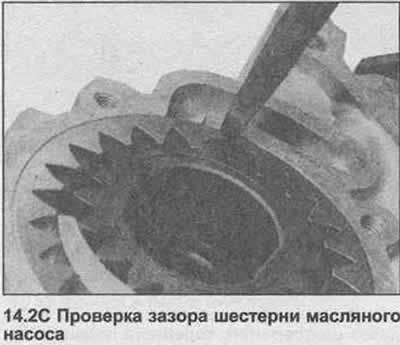
2. Use a feeler gauge to check the backlash of the two gears, then check the backlash between the two gears (photo).
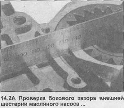
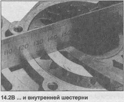
3. If any value is outside the specified tolerances, it is recommended to replace the oil pump, although individual parts of it are also available.
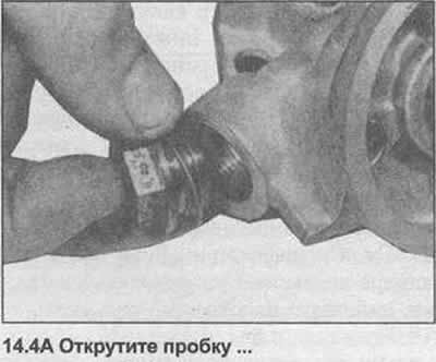
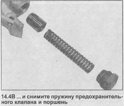
4. Unscrew the plug, remove the safety valve spring and piston (photo). Check their condition.
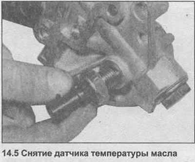
5. If necessary, unscrew the oil temperature sensor (photo).
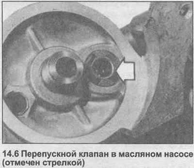
6. Check that the bypass valve ball is correctly positioned (photo). If necessary, pull out the old valve and press in the new one.
7. Completely clean all components, then reassemble them in reverse order, use a new plug seal (photo).
Crankshaft
8. Check the condition of the surfaces of the main and connecting rod journals of the crankshaft, check the ovality and taper of the connecting rod fingers and main journals. If the dimensions of the working surface of the bearing do not fall within the tolerance ranges given in the Specifications at the beginning of the Section, the main and / or connecting rod journals must be reground.
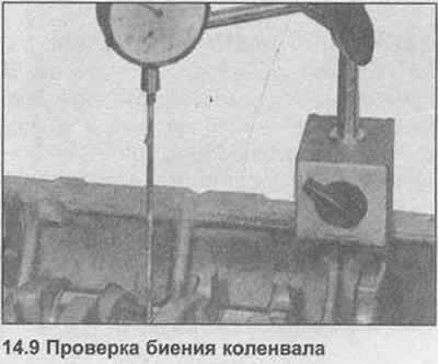
9. Check the runout of the crankshaft by installing it in the crankcase using only the front and rear liners. With a micrometer on the central main journal, rotate the crankshaft (photo).
10. The wear of the lower head of the connecting rod and the neck of the crankshaft is accompanied by a distinct metallic detonation and also some decrease in oil pressure. Wear of the main bearing and main journal is accompanied by strong engine vibration, rumble and, again, loss of oil pressure.
11. If the crankshaft requires regrinding, take it to a specialist who will tell you the correct dimensions of the bearing repair shells.
12. On some engines, the crankshaft journals are reground during production to allow for large manufacturing tolerances.
Main and connecting rod bearings
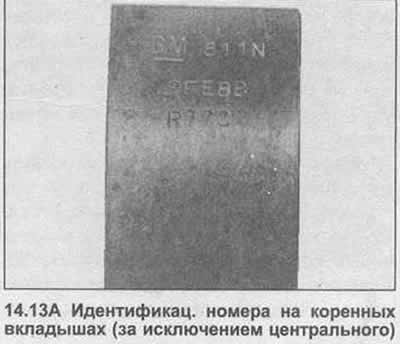
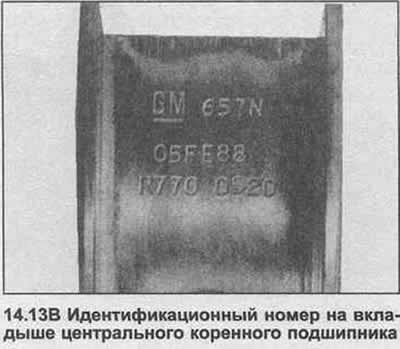
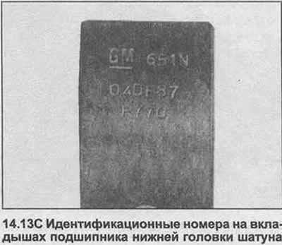
13. Check the condition of the main and connecting rod bearings. Inserts must be matte. If there are traces of copper, the bearings are badly worn. Replace them if they are in poor condition or if there are nicks or pitting. It is strongly recommended to replace bearings regardless of their condition - during the overhaul. Installing used bearings is a false economy (photo).
14. Repair dimensions are designed for use on a reground crankshaft. The bearings are in fact slightly larger than the stated outer dimension as running clearances are allowed.
Cylinder channels
15. Cylinder bores should be checked for taper, ovality, nicks and scratches. Carefully examine the top of the cylinder bores. If they are worn, you will find a small ridge on the thrust side. It is formed at the top of the piston stroke. Excessive oil consumption accompanied by blue smoke from the exhaust can be caused by worn cylinder bores and piston rings.
16. Measure the diameter of the cylinder bore across the block, just below the ridge. This can be done with an internal micrometer (caliper). Compare it with the diameter of the base of the hole, which is not subject to wear. If there are no measuring instruments, use a piston without rings and measure the clearance between the piston and the cylinder wall with a feeler gauge.
17. See Specifications. If the wear of the cylinder exceeds the permitted tolerances, the cylinders must be bored out.
18. If the cylinders have worn to the maximum possible diameter, it may be possible to install special liners.
Connecting rods
19. Check the matching surfaces of the connecting rod caps, if there have been attempts to remove wear by grinding, the connecting rods must be replaced.
20. Visually check the straightness of the connecting rods, and if there is a suspicion of distortion, check them on special equipment at a service station.
Pistons and piston rings
21. If the pistons and/or rings are to be reused, remove the rings from the pistons.
22. Repeat the process for the second and third rings.
23. Mark the rings, or store them so that they are not mixed up when installing.
24. Inspect the pistons to make sure they are recyclable.
25. Clean the annular grooves using a piece of the old piston ring of suitable width.
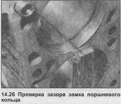
26. Check up that rings correspond to channels of cylinders. Insert the ring up to the unworn bottom of the hole (use a piston for this). Measure the ring gap clearance and check that it is within tolerance (see specs) (photo). Also check the backlash of the ring in the piston groove. If these measurements exceed the specified tolerances, the rings must be replaced, if the annular grooves in the pistons are worn, they must also be replaced.
27. It is possible to install piston rings that will reduce oil consumption due to hole wear without boring the cylinder during engine repair. Depending on the degree of wear, the improvement from the installation of such rings may be short-lived.
28. If new rings are installed (or pistons and rings), you need to remove the wear ridge at the top of the hole.
29. Check the gap and cut size of the new rings as described in step 26. If the ring is slightly pinched in the groove, it can be sanded down. If the gap of the cut is less than specified, it can be carefully widened with a file.
30. If new pistons are installed, they must be selected from the available (see specs) after measuring the cylinder diameter as described in point 16.
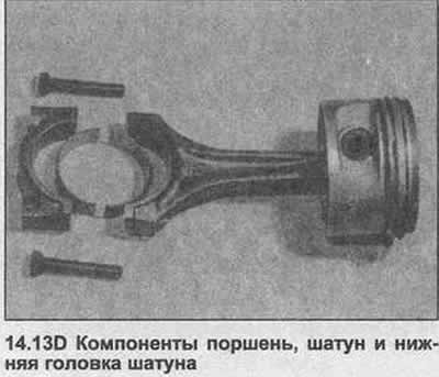
31. Removal and installation of pistons on the connecting rod - the work of a dealer or specialist. This requires equipment to remove and insert the piston pin.
Camshaft
32. With the camshaft removed, check the bearing surfaces for signs of wear. If there is wear, a new camshaft housing will be required.
33. The camshaft should not have any burrs on the surface of the cams or journals. If they are, replace the camshaft.
34. The fixing plate must be unworn and without grooves. In any case, check the side play of the camshaft, install a new plate where necessary.
Toothed belt drive
35. Carefully inspect the belt. If necessary, replace it. The belt must be replaced in any case at the intervals given in «Maintenance» at the beginning of this guide.
36. When reusing a toothed drive belt, always note the direction of rotation to prevent subsequent noisy operation.
Valve lifters, rocker arms and thrust pads
37. In case of wear, the valve lifter can only be replaced, since the block cannot be disassembled.
38. Examine a condition of a yoke and pads of axial pressure, replace in case of need.
Flywheel/Drive Disc
39. If the teeth on the starter ring gear are badly worn, it is possible to replace the ring gear on the flywheel.
40. Cut the ring. Be very careful not to damage the flywheel.
41. Clean and sandpaper four evenly spaced areas on the outer surface of the new starter ring.
42. Heat the ring evenly with a flame until the smooth parts turn dark blue. Alternatively, heat the ring in an oil bath to 200°C. Hold the ring at this temperature for five minutes and then quickly install it on the flywheel, with the groove toward the gearbox. Wipe off all oil from the ring before installing it.
43. The ring should cool down, after that check that it sits securely on the flywheel. Do not overheat the ring (do not heat it to light blue). If this happens, the ring will be released (will lose hardening).
44. If the flywheel clutch mating surface has nicks or crack marks caused by overheating, the flywheel surface can be re-sanded, as long as the overall thickness of the flywheel is not reduced too much. Consult a specialist and if this is not possible, replace the flywheel.
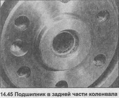
45 If the needle bearing in the center of the crankshaft flange is worn, fill it with grease and knock it out with hydraulic pressure. Insert the new bearing into place (photo).
Cylinder block
46. Check that the internal oil and grooves are free of sediment and not clogged.
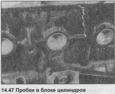
47. If the cork (photo) leaks, it can be replaced by inserting a screwdriver and removing it with a lever from the block. Clean the bearing surface, then hammer in a new plug with a drift or hammer. The use of a sealant is not required.
48. The crankshaft main bearing bolts and cylinder head bolts must be replaced.
Visitor comments