
Note: Manufacturers recommend using special tools for this procedure, although replacements can be made (described in text). It is recommended that you read this chapter carefully before starting work. Read the part again Chapters 1, giving information on cupped flywheels.
Removing
1. Where applicable, remove the left front wheel cover, then loosen the wheel bolts. Apply the handbrake, jack up and support the front of the vehicle on axle stands. Remove the wheel for better access. On models with double overhead camshafts (DOHC) Remove the bottom engine skid plate as described in Section 11.
2. Remove the mounting bolts and remove the protective cover from the base of the clutch housing.
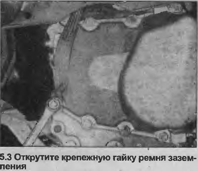
3. Loosen the mounting nut and disconnect the ground strap from the transmission end cap (see illustration).
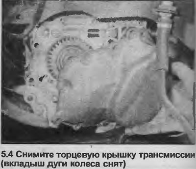
4. Place a container under the transmission end cover to catch the oil, then unscrew the mounting bolts and remove the cover (see illustration). Mark the position of the bolt securing the ground strap. To improve access, remove the wheel arch insert as described in Section 11.
5. Remove the gasket.
6. Remove the circlip from the recess at the end of the input shaft using special pliers.
7. Using a hex key, remove the screw from the end of the input shaft.
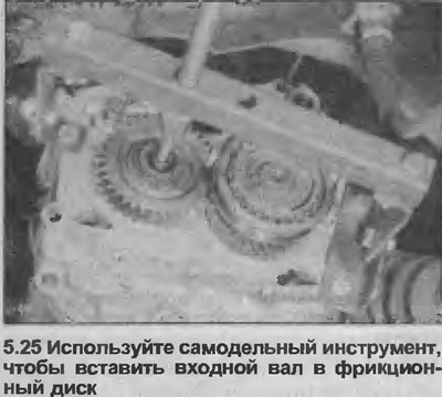
8. Remove the input shaft from the clutch friction disc hub. For this procedure, manufacturers recommend using tools No. KM-556-1-A and KM-556-4, but a replacement can be made (see illustration). The tool is attached to the transmission with end cap bolts (see illustration 5.25). The dimensions of the tool depend on the type of transmission.
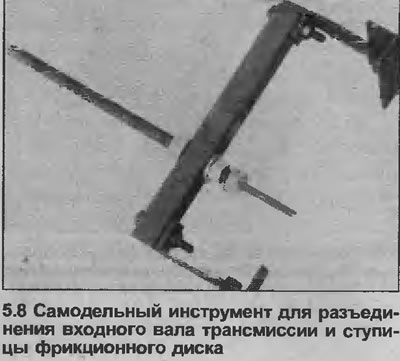
9. Alternatively, screw an M7 bolt into the end of the input shaft and use it to drive the shaft out (to the border). The input shaft can be very tight and cannot be removed without the help of the special tool described above. In some cases, a slide hammer can be used.
10. Before removing the clutch assembly, the pressure plate must be displaced against the pressure of the diaphragm spring, otherwise the assembly will be too thick and will not fit between the flywheel and the edge of the clutch housing.
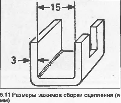
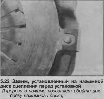
11. There are special clamps for this purpose (tool No. KM-526-A), but a replacement can be made from metal strips. Clamps must be U-shaped and according to the dimensions given below (see illustration). File down the edges of the clips to make installation easier, and cut a groove in one of the folded ends to bypass the pressure plate rivets.
- a) Strip thickness - 3.0 mm
- b) Distance between folded ends - 15.0 mm
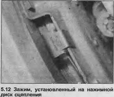
12. Have an assistant fully depress the clutch pedal, then securely position the clips around the edge of the housing/pressure plate by inserting the clips into the openings on the periphery of the housing (see illustration). Rotate the crankshaft with a wrench on the sprocket bolt to gain access to the location of each of the clips.
13. Once the clamps have been installed, have an assistant release the clutch pedal.
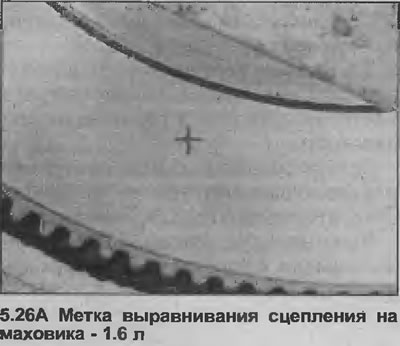
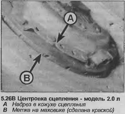
14. Gradually loosen and remove the six bolts and spring washers securing the clutch cover to the flywheel. Turn the crankshaft again to get to each of the bolts. Notice the position on the flywheel of the mark that aligns with the notch on the clutch cover.
15. Remove the clutch assembly from the clutch housing (down) (see illustration). Be prepared to catch the friction disc that may fall out of the cover when the clutch is removed, and remember the correct location of the friction disc. The side of the hub with the smaller protrusion should face the flywheel.

16. To remove the clamps, hold the clutch assembly in a vice with soft-toothed jaws.
17. Inspect clutch components for signs of wear and damage.
Inspection
18. Remove all traces of dust from the remote clutch assembly using a dry cloth. Although most friction discs are fitted with asbestos-free linings, it is recommended that precautions be taken not to inhale the dust being removed, as asbestos is harmful to health.
19. Inspect friction disc linings for signs of wear and broken rivets. Check disc for warping, cracks, broken damper springs, and worn slots. The surface of the friction linings may be worn, but if the texture of the material is still visible, the condition of the lining is considered satisfactory. If there are any signs of oil or grease contamination (shiny black spots), the disc must be replaced and the cause of the contamination found and repaired. Usually the source of contamination is either a leaking crankshaft oil seal or a transmission input shaft oil seal (or both). Procedures for replacing them are given in Sections 2A, 2B and 7 (depending on the model). The friction disc must also be replaced if the lining has worn down to the rivet heads (or close to them).
20. Inspect the surfaces of the flywheel and pressure plate. If they have deep scratches or notches, they need to be replaced. The pressure plate should also be replaced if it is cracked or if the diaphragm spring is damaged or weak.
21. While the clutch is removed, it is recommended to check the condition of the release bearing as described in Chapter 7.
Installation
Note: When reassembling, use a new circlip (input shaft end) and the transmission end cover gasket.
22. Sometimes a New Clutch Assembly is Already Clamped (see point 11). If this is not the case, compress the assembly yourself. Clamp the assembly in a vise with soft-grip jaws and install the clamps used during removal (see illustration).
23. Make sure the friction plate linings and the surface of the pressure plate and flywheel are free of oil or grease. It is recommended that you install the clutch assembly with clean hands and wipe the surface of the pressure plate and flywheel with a clean rag.
24. Apply a small amount of molybdenum grease to the grooves of the friction disc hub. Then install the disc on the flywheel with the side of the hub with the smaller protrusion toward the flywheel. Press the friction plate against the flywheel and install the shroud/pressure plate assembly in place.
25. Insert the input shaft into the friction disc hub so that its end enters the bearing at the end of the crankshaft. Never drive the shaft into place with a mallet or similar tool, as this may damage the transmission. If the input shaft cannot be installed manually, the manufacturers suggest using a special tool (No. KM-564). The homemade tool used to remove the shaft can also be used (to do this, you need to move the nut) (see illustration).
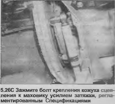
26. With the input shaft in place, position the housing/pressure plate assembly so that the mark on the flywheel aligns with the notch in the clutch housing. Install and progressively tighten the six bolts in diagonal sequence (and spring washers) attaching the clutch cover to the flywheel (see illustrations). Rotate the crankshaft with a wrench on the sprocket bolt to gain access to each bolt in turn, and finally tighten all the bolts to the specified torque specifications.
27. Have an assistant depress the clutch pedal, then remove the three clips from the edges of the casing/pressure plate while turning the crankshaft again to access the clips.
28. As soon as clips are removed, ask the assistant to release a coupling pedal.
29. Install a socket head cap screw into the end of the input shaft, then install a new circlip.
30. Using a new gasket, install the transmission end cover and tighten the mounting bolts with a tightening torque regulated specifications. Make sure the bolt securing the ground strap is in the correct location (marked upon removal).
31. Install the ground strap on the transmission and tighten the mounting nut.
32. Install the cover on the base of the clutch housing and tighten the mounting bolts. Where applicable, install wheel arch insert. On models with double overhead camshafts (DOHC) install the lower engine protection plate.
33. Install the wheel, then lower the vehicle to the ground and finally tighten the wheel bolts. Install cap where applicable.
34. Check clutch cable adjustment as described in Chapter 3.
35. Check and, if necessary, top up the gear oil level as described in Section 1.
Visitor comments