
Removal
1. A specific feature of the models under consideration is that they can replace the clutch pressure and driven discs, the release bearing, the clutch release lever bushings and the bearing guide seal without removing the engine or gearbox from the car.
2. The manufacturer recommends using special tools for this work, but in principle you can do without them.
3. Some of the operations are best done while working under the front of the machine, so you should apply the handbrake and jack up and support the front end. Unscrew and remove the flywheel housing cover bolts from the clutch housing base.
4. Unscrew and remove the plug from the end cover of the gearbox housing (see photos).
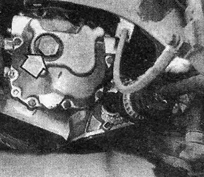
Photo 5.4A. Screw plug on the end cover of the 4-speed gearbox (shown by arrow).
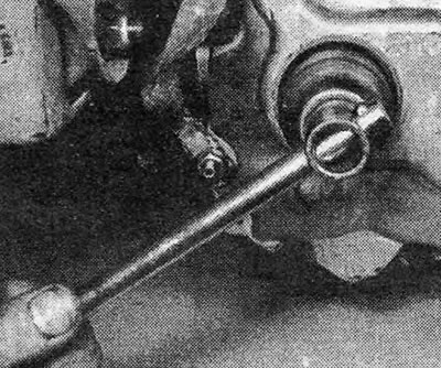
Photo 5.4V. Removing the screw plug (4-speed gearbox).
5. Using special pliers, remove the retaining ring from the end of the transmission drive shaft (see photo).
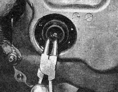
Photo 5.5. Removing the retaining ring from the transmission drive shaft.
Pic. 5.5. Removing the clutch
6. Under the locking ring there is a screw with a hole in the head for a 12-point socket, to remove which you will need a 12-point wrench (see photos).
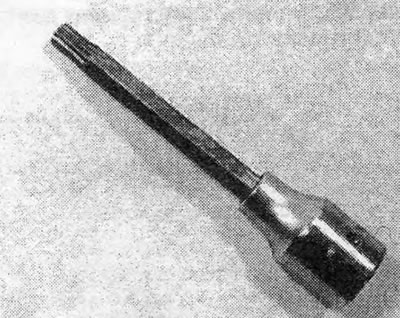
Photo 5.6A. A dowel wrench used to remove special bolts.
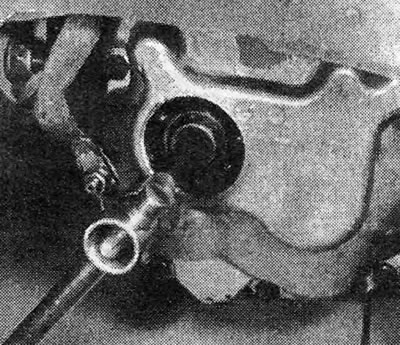
Photo 5.6V. Removing the gearbox drive shaft screw.
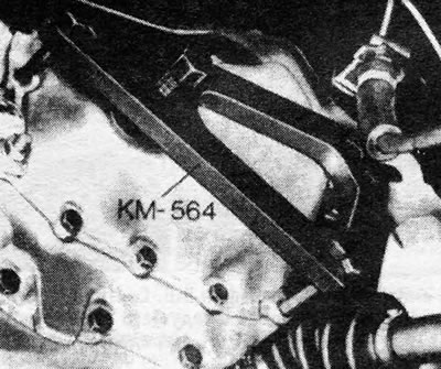
Pic. 5.6. Tool KM-564 for installing the gearbox drive shaft into the clutch driven disc
7. In order to remove the drive shaft of the box from the splinted hub of the clutch driven disc, a special tool is required, but you can do without it. Remove one of the 4 bolts securing the gearshift cover to the gearbox housing, and, using it as a sample, select the same bolt, but at least 40.0 mm long. Screw this bolt into the end of the drive shaft of the box and, holding it, pull out the shaft. When finished, screw the removed bolt back into place (see photos). On some 5-speed transmission models, the drive shaft has a very tight fit and will require a special tool or puller to remove it. In extreme cases, you can install a reverse hammer on the end of the shaft and use it to remove the shaft.
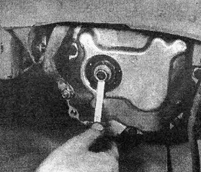
Photo 5.7A. Screw the bolt into the drive shaft.
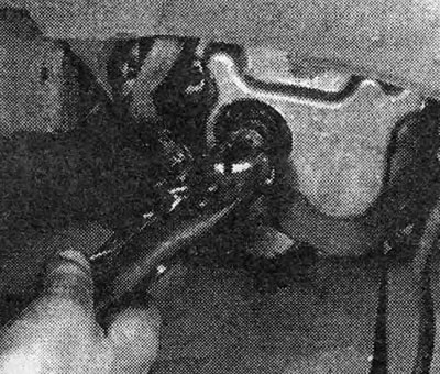
Photo 5.7V. Removing the drive shaft.
8. Before you can remove the clutch, you will need to press the pressure plate against the pressure of the diaphragm spring, because otherwise, the dimensions of the clutch basket will not allow it to be pulled into the gap between the flywheel and the edge of the clutch housing.
9. The manufacturer offers three special clamps (KM526) to press the pressure plate, however, similar clamps can be made independently from strips of metal. The clamps must be U-shaped and meet the following requirements:
- Metal strip thickness = 3.0 mm
- Distance between clamp legs = 15.0 mm (see photos).
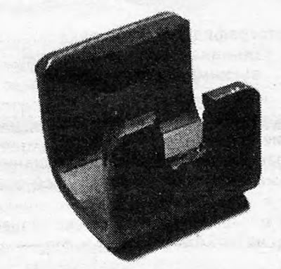
Photo 5.9A. Clamp for holding the clutch basket in a compressed state.
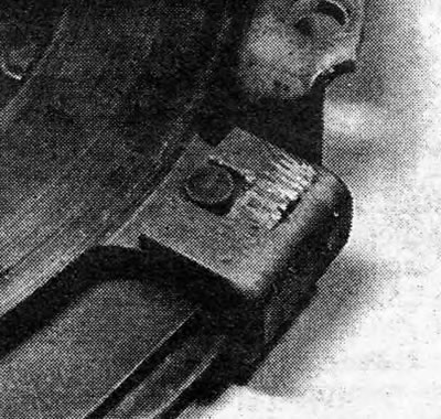
Photo 5.9V. Clamp for holding the clutch basket in a compressed state (view from the pressure plate side).
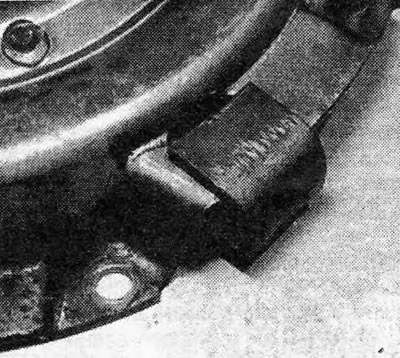
Photo 5.9C. Clamp for holding the clutch basket in a compressed state (view from the clutch housing).
10. Make chamfers on the legs of the clamps to make them easier to install. Have an assistant press the clutch pedal all the way and install the clamps on the clutch basket by inserting them into the holes provided along the edges of the clutch housing. To make this easier, you should turn the crankshaft using a wrench placed on the bolt of its pulley.
11. After installing the clamps, release the clutch pedal.
12. Gradually loosen and remove the 6 bolts securing the clutch housing to the flywheel (see photo).
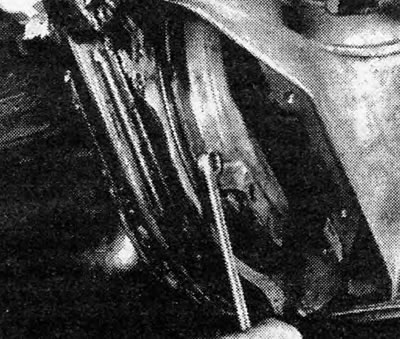
Photo 5.12. Removing the clutch housing bolts.
13. The models in question do not have locating pins that would fix the position of the clutch housing relative to the flywheel. Instead, you need to make sure that the colored dot on the flywheel is aligned with the notch on the rim of the clutch housing.
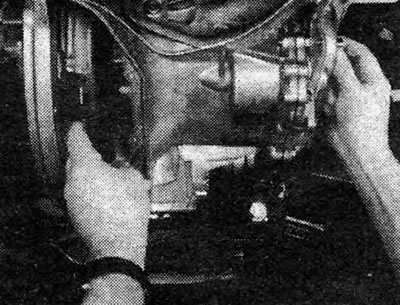
14. Pull the clutch out of the housing through the bottom. In order to be able to remove the clamps, you will have to press the pressure plate in a vice (see photo).
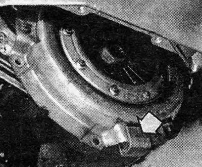
Photo 5.14. Removing the clutch with the clamps installed.
Inspection
15. Under normal conditions, rebuilding the clutch involves installing new pressure and driven disks and a release bearing. Under no circumstances should the diaphragm spring assembly be disassembled. If the clutch basket is faulty, it is replaced as an assembly.
16. Do not attempt to replace the friction linings of the driven disk. A disc with linings worn down to the rivets or with oily linings must be replaced. If the linings are oily, you should find and eliminate the oil leak before installing a new disc (it could be a leaking engine or transmission seal). The driven disc may also have damage in the form of broken torsion springs or worn disc hub splines.
17. When installing a new clutch, we recommend replacing the release bearing at the same time (see section 7).
18. Inspect the surfaces of the flywheel and pressure plate. If there are grooves on them, the surfaces must be sanded. In extreme cases, the flywheel or pressure plate must be replaced. The pressure plate must also be replaced if it has cracks or splits.
Installation
19. In some cases, the new clutch is delivered already compressed, with clamps installed. If there are no clamps, you should press the pressure disk in a vice, using spacers to avoid damaging the ground surfaces of the disk. Alternatively, you can press the pressure plate using a bolt and nut and two metal strips with holes drilled in them. After pressing the disk, install the clamps.
20. Apply a little molybdenum disulfide grease to the splines of the driven disk hub and place it on the flywheel with the protruding part of the hub away from the flywheel. Holding the driven disc in this position, install the clutch basket (already compressed, with clamps installed).
21. Insert the drive shaft of the box into the hub of the driven disk so that its end engages the guide bearing at the end of the crankshaft. It is forbidden to hammer the shaft into the driven disk with a hammer, because this may damage the transmission.
22. If you cannot install the drive shaft manually, it must be pressed using the special tool KM-564 (see fig.5.6). You can make a similar tool yourself.
23. Attach the clutch housing to the flywheel with bolts and tighten the bolts to the required torque.
24. Have an assistant press the clutch pedal and remove the temporary clamps from the clutch.
25. Screw the screw into the end of the transmission drive shaft and install a new snap ring.
26. Only on models with a 4-speed gearbox, apply sealant to the threads of the plug and screw it into the gearbox end cover. Tighten the plug to the required torque. A correctly installed plug should protrude no more than 4.0 mm above the surface of the end cap (see photo).
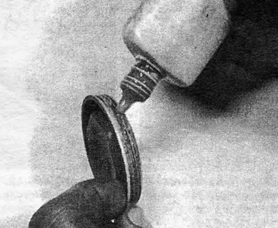
Photo 5.26. Apply sealant to the threads of the end cap plug (4-speed gearbox).
27. Check clutch adjustment (see section 2).
28. Install the cover on the flywheel housing.
29. Lower the front of the car to the ground.
Visitor comments