
Warning: Clutch wear dust deposited on parts may contain asbestos which is harmful to health. DO NOT blow it off with air compression and inhale this dust. DO NOT use petrol (or gasoline-based solvents) for dust removal. Use a brake cleaner or denatured alcohol to flush out the dust in the container. After wiping the clutch elements dry with a rag, discard it in a labeled sealed container.
Note: Some engines (1.6 l and with two camshafts) factory equipped with flywheel type "pot", which is much thicker than usual. It cannot be removed unless the engine is removed from the gearbox. Check which flywheel is installed on the engine.
Models with standard flywheel
Note: Manufacturers recommend the use of special tools in this case, although suitable tools can be used.
Removing
If necessary, remove the left front wheel cover and loosen its bolts. Apply the handbrake, raise the front of the vehicle and jack it up securely under the drive axle. Remove wheel for access. On twin cam models, remove the lower engine mudguard.
Turn away bolts and remove a cover of a bell-shaped case of coupling.
For better access, remove the wheel arch trim as directed in chapter 11.
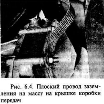
Unscrew the clamp nut and disconnect the ground flat wire from the transmission cover, if required (pic. 6.4).
Place a suitable container under the gearbox cover to collect the oil, then unscrew the bolts and remove the cover. Note the location of the bolts (including ground to ground if required), because two bolt sizes are used (pic. 6.5).
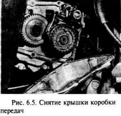
Remove the gasket.
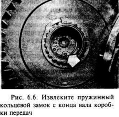
Remove the circlip-lock on the inside of the gearbox input shaft using special pliers (pic. 6.6).
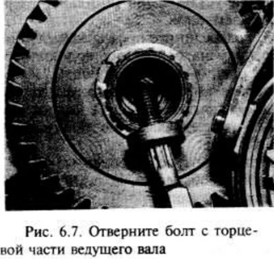
Using a hex wrench, unscrew the bolt from the end of the drive shaft (pic. 6.7).
The drive shaft can now be disengaged from the splined bushing of the clutch friction disc. Manufacturers offer tools for this work (No. KM-556-1-A and KM-556-4), however, you can use a homemade device (pic. 6.8).
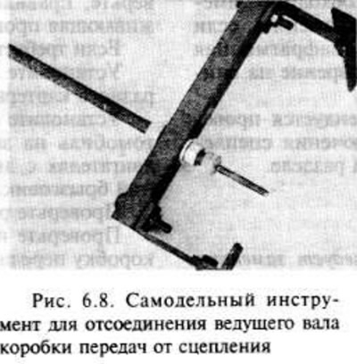
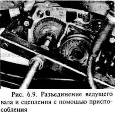
Alternatively, an M7 bolt can be screwed into the end of the input shaft and used for extraction.
Before removing the clutch assembly, press the pressure plate, otherwise the entire assembly will not pass through the gap.
Manufacturers produce three special clamps for this purpose (tool No. KM526-A), however, a suitable fixture can be made from a metal strip. The clamps must be U-shaped and meet the dimensions below.
The thickness of the metal strip is 3.0 mm.
The distance between the shoulders is 15.0 mm.
Have an assistant depress the clutch pedal all the way. Fasten each clip around the periphery of the pressure plate. Rotate the crankshaft with the appropriate wrench and sprocket/pulley bolt to check the location of each clip (pic. 6.10).
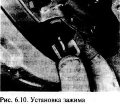
After installing the clamps, the clutch pedal is released by an assistant.
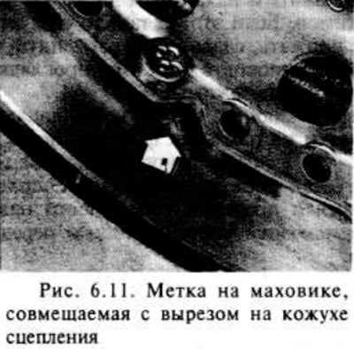
Gradually loosen and remove the six bolts with spring washers that secure the clutch cover to the flywheel. Rotate the crankshaft to access each bolt. If it is necessary to install an old clutch, note the position of the mark on the flywheel aligned with the mark on the rim of the clutch housing (pic. 6.11).
The clutch assembly can now be removed from the bell housing. Be careful not to miss the clutch friction disc, which may fall out, and note its circular position. The protruding part of the hub looks in the opposite direction from the flywheel.
The pressure plate can be squeezed in a soft-spaced vise when removing the clamps.
Examination
After removing the clutch, remove all traces of dust with a dry cloth. Take precautions. because asbestos (on some patches) unhealthy.
Check the clutch disc lining for wear and loose rivets or damage. cracks, burst torsion springs and worn splines. If there are signs of oil contamination in the form of spots, the disc should be replaced. The source of contamination should be identified and eliminated before installing new clutch elements. A typical case is oil leakage through the crankshaft oil seal or gearbox input shaft oil seal (chapters 2 and 7 respectively). The disc should also be replaced when the friction linings are worn to the point where the rivet heads protrude above or close to the end face of the lining.
Check machined surfaces of flywheel and pressure plate. If they have grooves, scratches, etc., they must be replaced. The pressure plate should also be replaced if it is cracked, or if the diaphragm spring is damaged, or there is a suspicion of a decrease in its pressure.
After removing the clutch, it is recommended to check the condition of the clutch release bearing as indicated in the next section below.
Installation
Note: During reassembly, the transmission cover gasket and the circlip on the end of the input shaft should be replaced.
Some replacement clutch assemblies come pre-compressed with three clamps on the pressure plate. If this is not the case, then press the pressure plate by squeezing the diaphragm spring with a vice with soft pads on the jaws, and install the clamps.
Make sure that no oil or grease gets on the friction plate linings or on the pressure plate and flywheel surfaces. It is recommended that you install the clutch assembly with clean hands and wipe the surfaces of the pressure plate and flywheel with a clean rag before assembling.
Apply grease (molybdenum disulfide) on the splines of the hub of the friction disc, then bring the disc to the flywheel so. so that the protruding part of the hub is directed away from the flywheel. Press the friction plate against the flywheel and at the same time move the cap/pressure plate assembly into place.
The drive shaft can now be pushed through the friction disc hub until it engages with the bearing at the end of the crankshaft, under no circumstances should a hammer be used to install the shaft, as this may damage the gearbox. If the drive shaft cannot be installed manually, a special tool must be used (N KM-564), However, you can use a homemade device for this. already used to remove the shaft.
With the drive shaft in place, position the cover/pressure plate assembly so that the mark on the flywheel aligns with the notch on the clutch cover rim, then install and gradually tighten diagonally the six cover-to-flywheel bolts (checking the installation of spring washers). Rotate the crankshaft with the appropriate wrench and sprocket/pulley bolt to gain access to each bolt in turn. Finally, tighten all bolts to the required torque.
Have an assistant depress the clutch pedal, then remove the three clips from the edges of the cover/pressure plate, rotate the crankshaft again to access each clip.
After removing all the clips, release the clutch pedal.
Install the screw on the end of the transmission input shaft and install a new circlip.
Establish a cover of a transmission and tighten bolts the demanded moment. If required, check that the stud holding the ground wire is properly installed.
If required, connect a ground wire.
Install the cover on the base of the clutch bell housing and tighten the bolts.
Install the road wheel, then lower the vehicle to the ground and tighten the wheel bolts. On engines with two camshafts, install the lower mudguard.
Check clutch cable adjustment.
Check and, if necessary, add oil to the gearbox to the required level.
Models with flywheel type "pot"
Removing
Due to the dimensions of this type of flywheel, it is not possible to pull the clutch out through the hole in the bell housing as previously stated for models with a standard flywheel.
If you do not completely remove the engine / transmission assembly from the vehicle and do not separate them for repair (chapter 2), the clutch can be accessed by removing the engine (chapter 2) or gearbox (chapter 7).
After removing the engine or gearbox, the operation procedure is as follows.
If you want to (and if the previous clutch is installed), note the position of the mark on the flywheel. which aligns with the notch on the rim of the clutch cover, then gradually remove the six bolts with spring washers that secure the clutch cover to the flywheel.
After removing all bolts, remove the clutch assembly. Be prepared to grab the friction disc while removing the cover from the flywheel and notice its circular position. The protruding side of the hub should face away from the flywheel.
Examination
The work procedure is the same as for models with a standard flywheel in this section (subsection "Examination").
Installation
The procedure for carrying out the work is as indicated in the two paragraphs above regarding the cleanliness of the assembly and the application of lubricant.
Install the clutch cover assembly where required, aligning the mark on the flywheel with the notch on the cover rim. Insert six bolts and spring washers and hand tighten.
Now the friction disc can be centered in such a way that when the engine is coupled to the gearbox, the splines of the gearbox input shaft pass through the splines of the friction disc hub.
Centering can be done by inserting a round bar (kernel) or a long screwdriver into the center hole of the friction disc so that the end of the bar enters the crankshaft centering bearing. Take measures to prevent damage to the bearing.
Tighten the cover bolts gradually in a diagonal tightening sequence to the required torque.
Install engine or gearbox, as indicated in the relevant chapter.
After finishing work, check the adjustment of the cable (Chapter 1).
Visitor comments