
Note. This work is painstaking, and in many cases it is easier to remove the gearbox along with the engine, as indicated in chapter 2. If you remove the gearbox separately, we suggest that you carefully read this section before starting work. You will have to replace various parts during assembly, you will need the appropriate equipment to support the engine, as well as a special tool to engage the drive shaft of the gearbox with the clutch.
Removing
Disconnect the negative battery terminal.
Working in the engine compartment, loosen the shift lever rod and linkage bolt, then pull the lever tube toward the engine room bulkhead to disengage it from the linkage.
With the clip removed, disconnect the clutch cable from the clutch release lever by pushing it back against the bulkhead if necessary to disengage the cable. Remove the cable holder from the bracket on the transaxle case, then move the cable out of the way.
Disconnect the reverse light switch wire above the left transaxle housing front bracket.
If required, disconnect the wire from the vehicle speed sensor.
Unscrew the clamping sleeve and disconnect the speedometer cable from the top of the gearbox.
Remove the top three bolts securing the engine to the gearbox, noticing the location of the brackets or clips.
Now the engine must be suspended from the left bracket. The ideal option would be to fix it on a solid wooden or metal beam, supported by blocks securely fixed in the channels on the sides. For this, a special proprietary device is used.
Raise the front of the vehicle and support it securely with stands under the drive axle so that the transmission can be pulled out.
On engines with two camshafts, remove the lower mudguard of the engine.
After making sure that the engine is secured, remove the front suspension subframe.
Drain the gearbox oil.
Now you need an appropriate tool to remove the inner ends of the drive shafts of the axle shafts from the differential. To remove the right drive shaft, you can use a flat steel bar with a rounded end. On some models, a square bar will be required to remove the left drive shaft.
Insert a lever between the drive shaft and differential housing to remove the circlip. Oil leakage is possible even if the gearbox oil is drained. Do not allow the drive shafts to hang under the weight of the weight, so tie them up.
If required, loosen the locknut and disconnect the ground flat wire from the transaxle end cap.
Substituting the container to collect the oil, unscrew the bolts and remove the cover. Remember the location of the bolts (and hairpins), because two bolt sizes are used.
Remove the gasket.
Remove the circlip from the end of the transmission input shaft using special pliers.
Using a wrench, remove the bolt from the end of the drive shaft.
Now the shaft can be disengaged from the splined hub of the clutch friction disc. Special tools KM-556-1-A and KM-556-4 are used, however, home-made devices can also be used (see more details. chapter 6).
You can also screw an M7 bolt into the end of the input shaft and use it to pull the shaft out until it stops.
Place a jack under the gearbox, and place wooden beams to evenly distribute the mass.
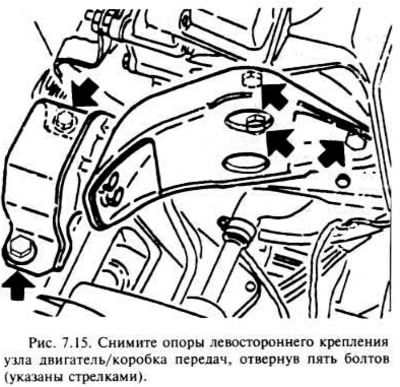
Remove the left-hand engine/gearbox mountings by unscrewing the two shim-to-vehicle body mounting bolts and the three bracket bolts on the transaxle.
Loosen the bolts and remove the cover from the base of the conical clutch housing.
After making sure that the gearbox is properly secured, remove the remaining engine and gearbox mounting bolts.
Now the gearbox can be lowered and pulled out from under the front of the car. With outside help, this is easier to do.
Installation
Before starting installation, make sure that the two old bolts of the left-hand side of the engine / gearbox assembly to the vehicle body rotate freely in the threaded holes in the body. If necessary, cut a new thread with an M10x1.25 mm tap.
Start installing the gearbox under the front of the car, jacking it up with wooden beams, as you did during removal.
Raise the transmission so that the lower engine/gearbox mounting bolts can be installed, then install but do not tighten.
Install the left side engine/gearbox mounts using the two new shim-to-body bolts. Tighten all bolts to the required torque.
Tighten the previously installed engine/gearbox assembly bolts to the correct torque, then move the mobile jack out from under the gearbox.
The transmission drive shaft must now be pushed through the clutch disc hub until it enters the center bearing at the end of the crankshaft. Under no circumstances should the shaft be driven into place with a hammer, as this may damage the gearbox. If the drive shaft cannot be inserted by hand, pressure must be applied to the end of the shaft. For this purpose, there is a special tool N KM-564, but you can use another device.
Install the bolt on the end of the drive shaft, install a new circlip.
Install the transmission end cover with a new gasket and tighten the bolts to specification. Check ground wire stud installation.
If required, connect the ground wire to the transmission ground and install the lock nut.
Install the flat cover on the base of the tapered clutch housing and tighten the bolts.
Install new circlips on the inner ends of the drive shafts, push them in the differential case as far as possible.
Install the front suspension subframe and then the front wheels.
Remove the lifting devices and lower the vehicle to the ground.
Install the top three engine-to-transmission bolts and tighten to specification.
Connect the speedometer flexible shaft and clamping sleeve.
If required, connect the wire to the vehicle speed sensor.
Connect the wire to the reverse signal switch.
Install the clutch cable holder on the gearbox housing, connect the cable to the clutch release lever and adjust the cable travel. Make sure the cable is in the same position as before removal.
Connect the shift fork stem to the linkage, adjust it before tightening the bolt.
Fill the gearbox with oil.
Connect the negative battery terminal.
Visitor comments