


Note: These operations are performed without removing the engine and gearbox from the engine.
Raise the vehicle and remove the clutch housing cover.
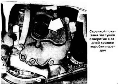
Unscrew the plug (see photo) of the rear cover of the gearbox.
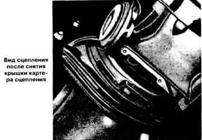
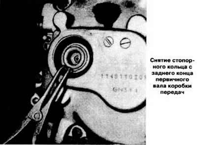
Remove the retaining ring and unscrew the rear screw from the gearbox input shaft (see photo).
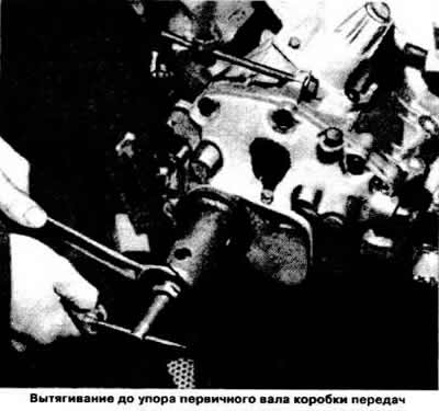
Using a puller, pull the primary shaft out of the gearbox until it stops (see photo).
Disconnect the clutch drive cable from the clutch release fork lever, having first removed the locking bracket.
Disengage the clutch and lock the clutch pedal in the depressed position.
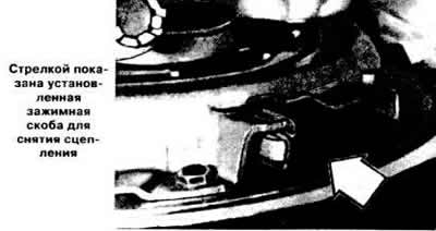
Clamp the clutch housing with KM 450 clamps on vehicles with gearbox types "F10", "F13" or KM 526 on vehicles with gearbox types "F16", "F20".
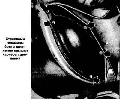
Loosen the bolts securing the clutch housing to the flywheel and remove the clutch housing together with the driven disk, removing them through the opening. This releases the driven clutch disk.
Loosen the bolt securing the clutch release fork to the lever and remove the clutch release bearing.
Remove the lever from the clutch housing through the top and remove the clutch release fork.
The clutch is installed in the reverse order of removal.
Replace the lever, bearing and clutch release fork.
Lubricate the splines of the clutch driven disk bushing with a thin layer of grease.
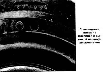
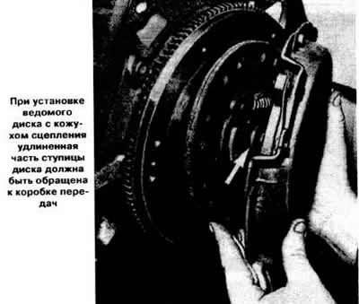
Put the driven clutch disc with the inscription in place "Getri-ebe seite" ("From the drive side") to the clutch housing. Install the clutch housing assembly with the driven disk on the flywheel, aligning the mark on the flywheel with the recess on the clutch housing (see photo), and screw on the mounting bolts.
Slightly lift the driven disk and, moving the disk away, insert the input shaft of the gearbox into the splines of the driven disk sleeve.
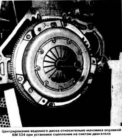
Note: If the clutch is installed on a removed engine, center the driven clutch disc relative to the flywheel using the KM 534 drift (see photo and drawing), simulating the splined end of the primary shaft of the gearbox.
Tighten the bolts securing the clutch housing to the flywheel.
Screw the rear bolt into the primary shaft of the gearbox and, using the KM 449.2 device, insert it until it stops.
Place a new retaining ring on the end of the gearbox input shaft.
Apply a special sealant to the thread of the plug or seal it with polyvinyl chloride film. To ensure tightness, screw the plug so that the distance between its end and the surface of the rear cover of the gearbox is no more than 4 mm.
Remove the three clamping brackets.
Replace the clutch housing cover.
Connect the clutch cable to the lever and secure it with a locking clip.
Check and, if necessary, adjust the clutch pedal travel as described below.
Lower the car.
Adjusting the Clutch Pedal Travel
The clutch pedal has no free travel, and its working travel increases as the driven disk wears out.
The clutch pedal stroke is subject to adjustment only if the clutch drive cable or the driven clutch disc is replaced. Measure the distance between the center of the clutch pedal and the steering wheel with the clutch pedal released and pressed with a ruler. Determine the difference between the results of the changes, which should be 138±7 mm. If necessary, remove the clutch drive cable locking bracket and, by rotating the cable end with which it is connected to the clutch release fork lever, achieve the required size. After adjustment, secure the cable with a locking bracket.
(Material copied from the portal: opelbook.ru)
Visitor comments