


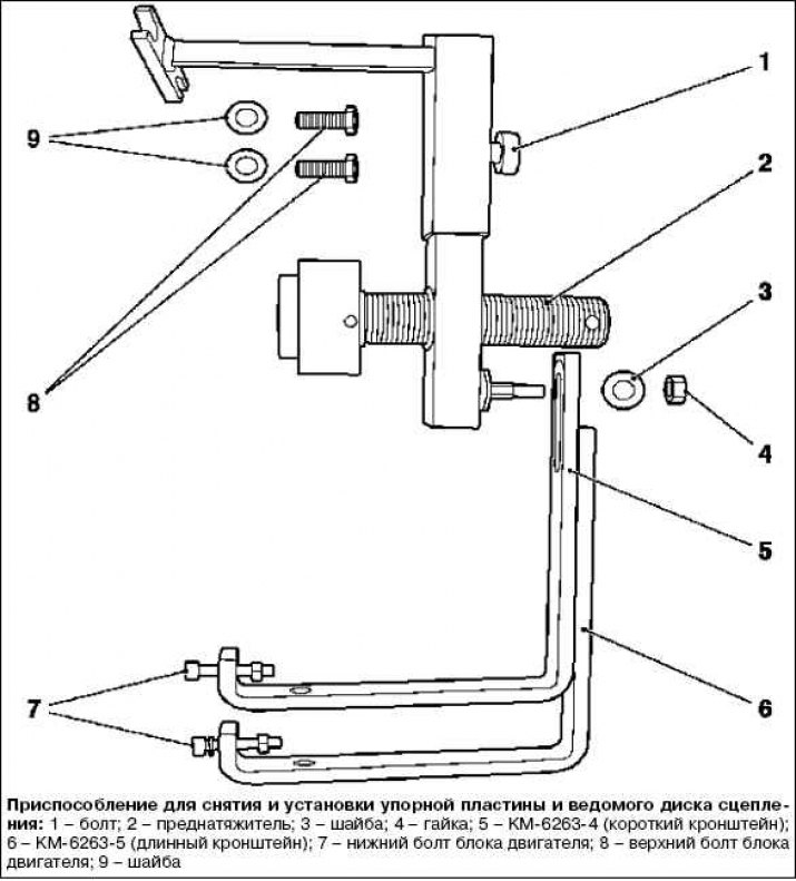
Note: To prevent damage to the thrust plate spring petals, use special tool KM 6263 during removal and installation.
Note: Please note the different lengths of the brackets for attaching the KM 6263 when lowering the engine block.
Removal
Remove the gearbox.
Note: Special tool KM 6263 can only be attached to the engine block, not to the oil pan.
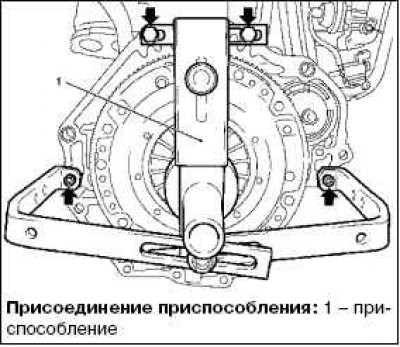
Attach the special tool KM 6263 to the engine block and tighten the 4 bolts (arrows in the picture).
Note: Do not tighten the bolts.
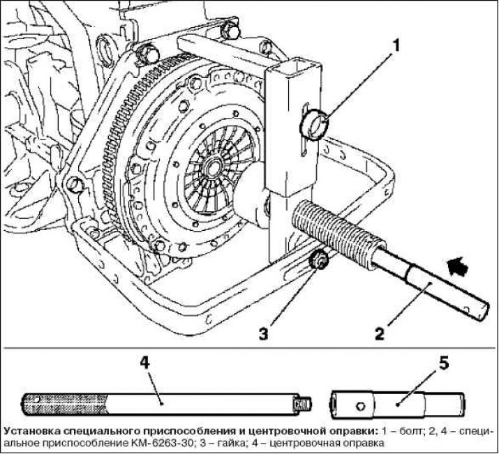
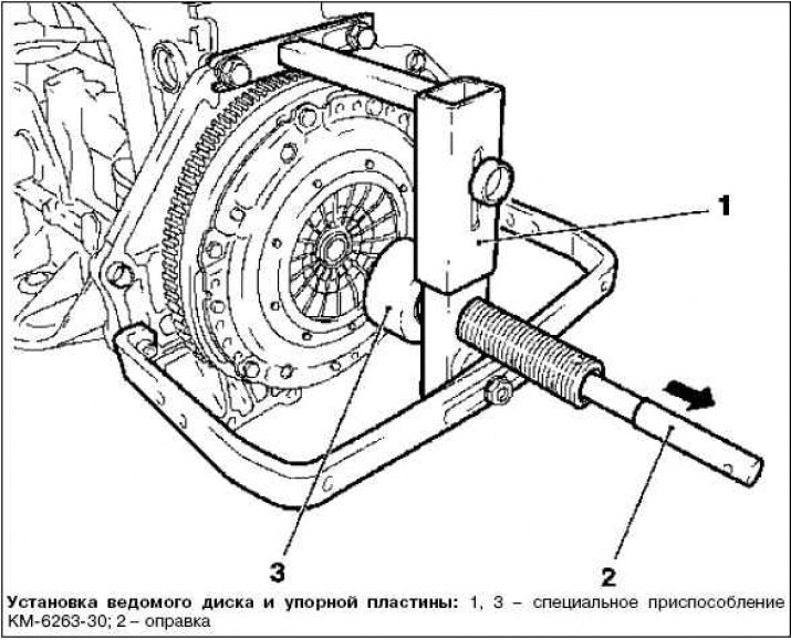
Attach special tool KM-6263-30 (4) to the centering mandrel.

Secure the special device KM 6263.
Align special tool KM 6263 with the center.
Install the centering mandrel with special tool KM-6263-30 through KM 6263 into the clutch disc and crankshaft (center).
Tighten the bolt and nut.
Tighten the 4 bolts of the special tool KM 6263 on the engine block.
Release the clutch slave disc.
Install the special device KM 6263 so that it is opposite the petals of the thrust plate spring.
Turn the special tool KM 6263 clockwise until it reaches the stop.
Remove the thrust plate from the flywheel.
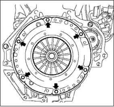
Unscrew the 6 mounting bolts (arrows in the picture).
Note: The figure shows the clutch without the special device KM 6263 and the centering mandrel.
Disconnect the thrust plate and clutch disc.
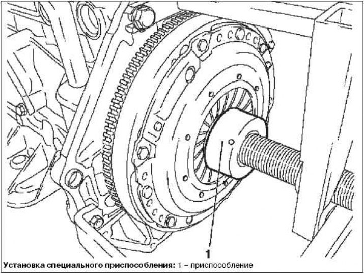
Turn the special tool KM 6263 counterclockwise to the stop and pull the centering mandrel out of the special tool KM-6263-30.
Examination
Check the thrust plate and clutch driven disc for wear.
Replace if necessary.
Note: Clutch discs contaminated with waste products (oil, cleanser, etc.) must be replaced. Check the clutch driven disc for damage and friction products on the hub and replace if necessary. Do not clean the thrust plate and clutch driven disc with a high-pressure cleaner or washing machine.
Check the condition of the flywheel friction surface for cracks, burns and surface wear.
Check the condition of the friction linings of the driven clutch disc and if there are traces of oil or mechanical damage, replace the driven disc.
Check the thickness of the clutch slave disk linings using a vernier caliper. The linings should protrude above the rivet heads by at least 0.3 mm.
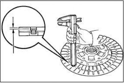
If the lining thickness is less than the permissible value or the rivet heads are close to the working surface, replace them or the driven clutch disc. Check that the springs are not broken or cracked. Check the splines in the clutch disc hub for wear.
Install the clutch disc onto the gearbox shaft.
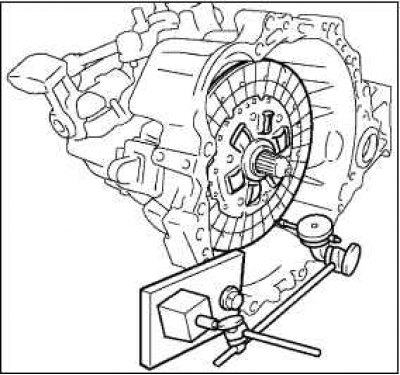
The driven clutch disc should slide easily and smoothly on the splines of the gearbox input shaft.
Attention! If the driven clutch disc is replaced, the clutch release bearing must also be replaced.
Using a dial indicator, check the clutch disc runout.
Minimum runout: 0.8 mm.
Using a vernier caliper, check the depth and width of wear on the diaphragm spring petals.
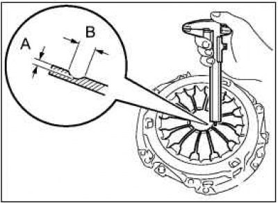
Maximum:
A (Depth): 0.5 mm
B (Width): 6.0 mm
Note: Minor damage to the friction surface can be removed with fine-grained sandpaper, but if there is any doubt about the condition of the pressure plate, it must be replaced with a new one.
(Original source on the website www.opelbook.ru)
Using a dial indicator, check the flywheel runout.
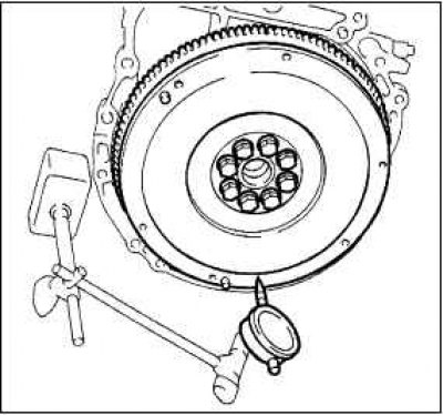
Maximum runout: 0.1 mm
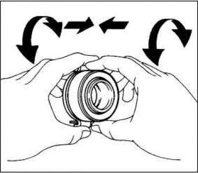
Rotate the clutch release bearing by hand, applying force in the axial direction, check the clutch release bearing.
Note: The bearing is lubricated for its lifetime, so additional lubrication is not required.
Note: If necessary, replace the clutch release bearing.
If new parts are installed, be sure to find out which pressure plate and driven plate are required by the engine designation and its number to avoid mistakes. If used clutch parts are installed, they must be checked beforehand.
Before installing a new pressure plate, the corrosion-protective grease must be removed only from the working surface. It is not recommended to remove the grease from other places under any circumstances, as this can significantly reduce the service life of the clutch.
Check the reliability of the installation of the centering pins on the flywheel.
Clean off the rust on the splined joint of the driven disk. Lubricate the teeth of the primary shaft of the gearbox with a thin layer of MoS2 grease. At the service station, G000100 grease is used for this purpose. After this, move the driven disk on the primary shaft so that the hub moves easily along the shaft. Be sure to remove excess grease.
Apply grease to the contact surfaces of the clutch release fork and sleeve, the fork and pushrod, and the fork support points.
Apply clutch spline grease to the drive shaft splines and clutch splines.
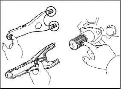
Install the clutch release fork with the clutch release bearing into the gearbox.
Note: After installation, move the fork forward and backward to check that the release bearing moves smoothly.
Installation
Note: The letter designation "Transmission side" must face the gearbox.
Attach the clutch slave disc and thrust plate to the flywheel.
Center the thrust plate and clutch disc using the centering mandrel and special tool KM-6263-30.
Note: For clarity, Figure 3.13 shows the clutch without the KM 6263 device.
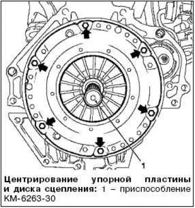
Tighten 6 new bolts (arrows in the picture).
Note: Do not tighten the bolts.
Attach the thrust plate to the flywheel.
Turn the special tool KM 6263 clockwise until it reaches the stop.
Tighten the 6 mounting bolts to 15 Nm.
Note: Tighten the bolts in a cross pattern.
Disconnect the special device KM 6263 from the engine block. Turn counterclockwise to the limiter and disconnect the centering mandrel and KM-6263-30.
Unscrew the 4 bolts of the special tool KM 6263 on the engine block.
Install the gearbox.
Visitor comments