


2. Insert the main bearing shells into the crankcase, the projections should enter the special grooves. Note that the central shell has axial pressure flanges.
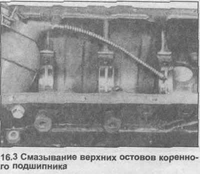
3. Lubricate the bearings with clean engine oil (photo).
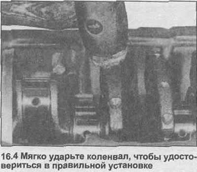
4. Carefully lower the crankshaft into the crankcase. Turn it a few times and check that it is seated correctly by gently tapping the crosspieces with a mallet (photo).
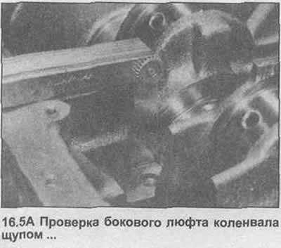
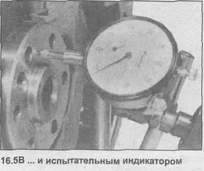
5. Check that the crankshaft lateral clearance corresponds to the data in Specifications, by inserting a feeler gauge between the ribbed central core of the main bearing and the thrust surface of the crankshaft, or by installing a test indicator on the flange of the rear of the crankshaft (photo).
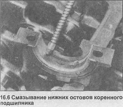
6. Clean the backs of the lower main bearing shells and caps, then install them in place. Lubricate the shells with clean engine oil (photo).
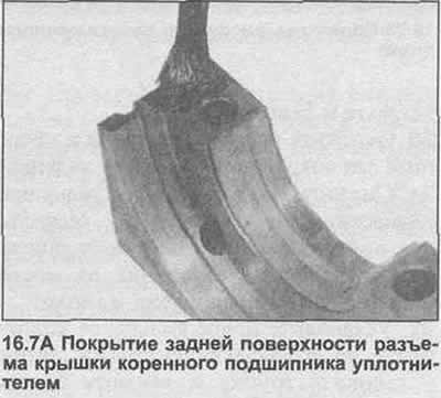
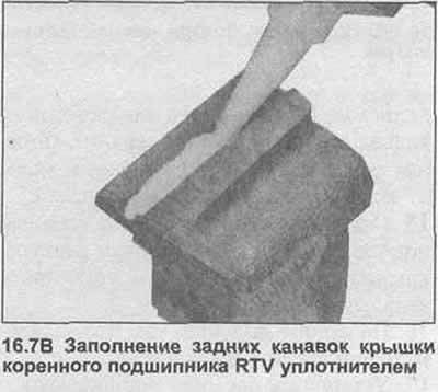
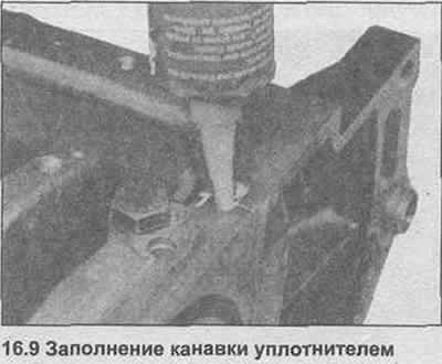
7. Coat the rear main bearing cap joint surface with GM 15 04 200 (8 983 368) sealant. Fill the side grooves of the cap with RTV compound or GM 15 04 294 sealant (90 001 851) (photo).
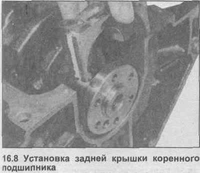
8. Install the rear main bearing cap, then insert new bearing cap mounting bolts and tighten them to the specified tightening torque Specification (photo) If required, a rear crankshaft oil seal can be installed.
9. Insert the sealant into the side grooves until they are filled (photo).
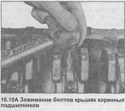
10. Install the remaining main bearing caps, then install the new cap mounting bolts and tighten them to the specified tightening torque Specification. Make sure that the plane of the front cover is even with the end of the crankcase. Note that the bolts must be tightened with an initial torque, then tightened to a certain angle (photo).
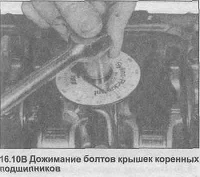
11. Turn the crankshaft and check that it rotates freely with no signs of binding or tight spots.
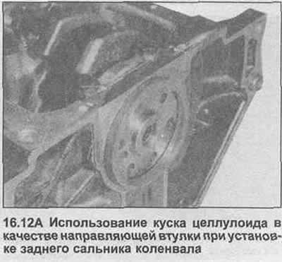
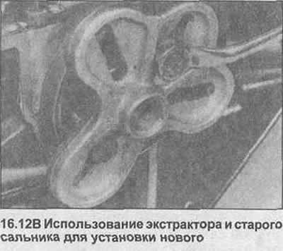
12. Lubricate the lugs of the new rear crankshaft seal. Cut a piece of celluloid to use as a guide bushing for the seal, place it on the rear flange of the crankshaft. Place the seal on the bushing, and insert it into the rear main bearing cap. You can use part of the pulley to press the seal in, using two flywheel bolts and the old seal (photo). Remove the extractor and celluloid.
13. Place the block on its side, lubricate the cylinder bores and crankshaft journals with oil.
14. Place the piston rings around the pistons so that their gaps are at 180°. In the case of the oil scraper ring, move the gaps in the upper and lower rails 25-50 mm to the right and left of the gap of the center section.
15. Clean the backs of the big-end bearing shells, caps and connecting rods, then install the shells in place.
16. Turn the crankshaft so that the journal of cylinder No.1 is at BDC.
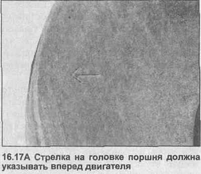
17. Fit a piston ring puller to piston No.1, then insert this piston into cylinder No.1 with the arrow on the piston head toward the front of the engine (photo). The extensions on the back of the piston, connecting rod and lower connecting rod bearing cap should face the rear of the engine.
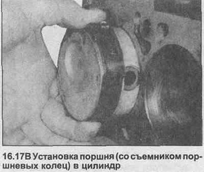
18. Using a hammer handle, drive the piston through the ring compressor, directing the connecting rod onto the journal.
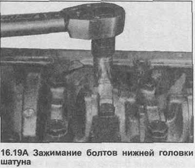
19. Install the lower connecting rod bearing cover, then insert the new lower connecting rod head bolts. Tighten the bolts first with the torque of Step 1, and then press down to the specified angle (see fig. Specifications at the beginning of this Section) (photo).
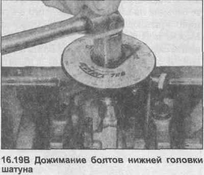
20. Check that the crankshaft rotates freely, taking into account the resistance of the piston rings.
21. Repeat the procedure given in steps 16-20 for the remaining pistons.
22. Turn the block over on the bench.
23. Place the new oil pump gasket on the front of the block, secure it with a small amount of grease (photo).
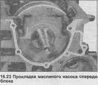
24. If necessary, remove the old oil pump seal.
25. Install the oil pump, then insert and tighten the bolts.
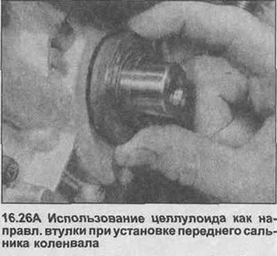
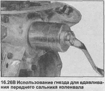
26. Cut a piece of celluloid and wrap it around the nose of the crankshaft. Grease the ridges of the new seal, position it on the celluloid. Using a suitable socket and the crankshaft pulley bolt, press the seal into place (photo). Remove the celluloid and socket.
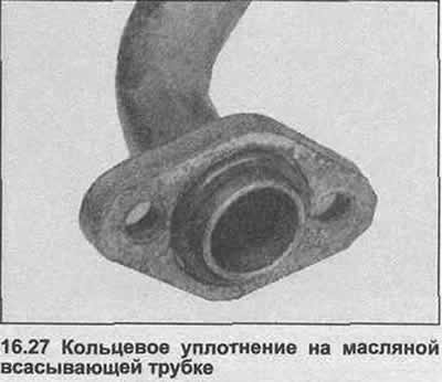
27. Install a new O-ring on the suction tube, then install the tube and tighten the bolts (photo).
28. Install the new pan gasket onto the bulkhead.
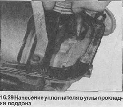
29. Apply sealant GM 15 03 294 (90 001 871) on both sides of the gasket in the corners only, place the partition on the crankcase (photo).
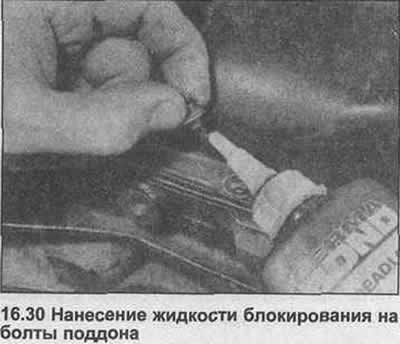
30. Install the pan. Apply locking agent to the bolt threads, then insert and tighten them evenly in a diagonal sequence to the specified tightening torque Specification (photo).
31. Place the engine stand on the workbench.
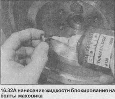
32. Position the flywheel/drive plate on the rear of the crankshaft. Apply thread locking compound to the threads of the new bolts, then insert and tighten them evenly, securing the flywheel in place using the method described in Chapter 9, paragraph 12. Note that the bolts must be tightened to the initial torque and then tightened to a certain angle (photo).
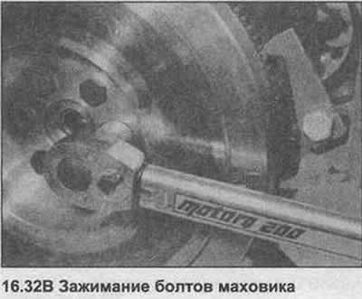
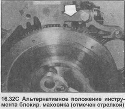
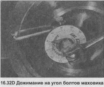
33. Turn the engine so that pistons No.1 and 4 are at TDC.
34. Check that the location pins are inserted into the block and that the connector surface on the block and cylinder head are clean (photo).
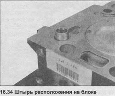
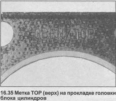
35. Place the new head gasket on the block with the TOP lettering facing up and forward (photo).
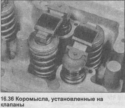
36. Install the hydraulic tappets, thrust pads and rocker arms into the cylinder head in their basic positions (photo). If new hydraulic tappets are used, first soak each one in a container of clean engine oil and squeeze by hand several times to fill them.
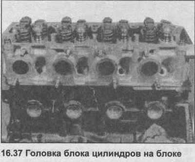
37. Place the cylinder head on the block so that the pins fit into the holes (photo).
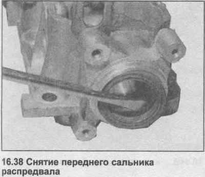
38. Remove the old seal from the front of the camshaft housing (photo). Clean the bearing surface, drive in the new seal using a block. Lubricate the seal projections with lubricant.
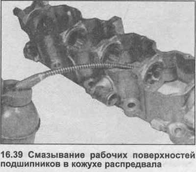
39. Lubricate the working surfaces of the bearing in the camshaft housing (photo).
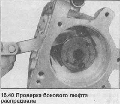
40. Carefully insert the camshaft into the housing. Install the camshaft retaining plate, tighten the bolts. Measure the lateral clearance of the camshaft with a feeler gauge (photo), compare it with the data in the Specifications.
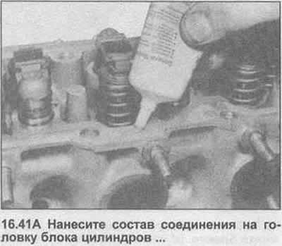
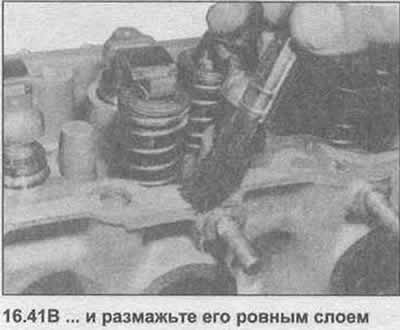
41. Apply the compound to the mating surface of the cylinder head, spread it evenly with a soft brush (photo).
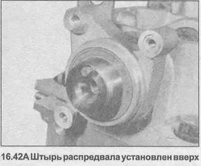
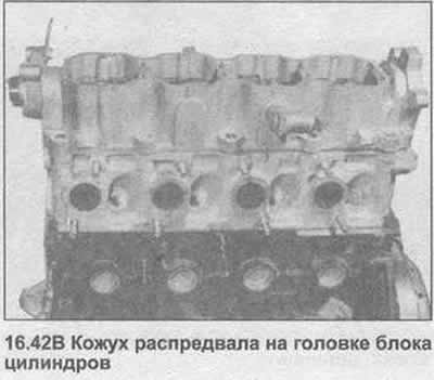
42. Turn the camshaft so that the pin in front is at the top (photo), then lower the camshaft housing onto the head.
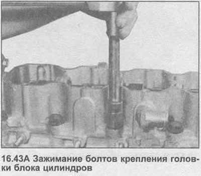
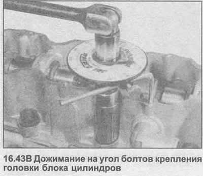
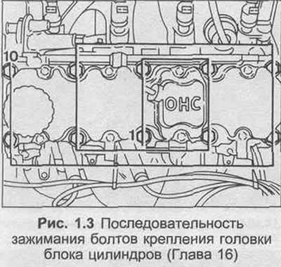
43. Insert new cylinder head mounting bolts, tighten them in the sequence shown in Figure 1.3 with the specified tightening torque Specification. Note that the bolts should be tightened to the initial torque, then gradually tightened to the specified angle (photo).
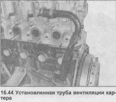
44. Install the crankcase ventilation pipe with a new gasket, tighten the bolts. Install the hose into the camshaft housing, tighten the clamps (photo).
45. Install the front coolant and thermostat housing to the cylinder head using a new O-ring. Insert and tighten the bolts.
46. Install the cooling fan hub hanger to the block. Insert and tighten the bolts.
47. Lubricate the O-ring on the new oil filter, then screw it into the oil pump housing by hand.
48. Install the rear timing belt cover. Insert and tighten the bolts.
49. Apply silicon lubricant or equivalent to the surface of the water pump that contacts the block. Install a new rubber O-ring.
50. Position the water pump in the block. Insert the clamp bolts and washers.
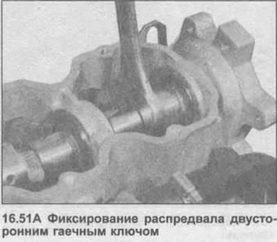
51. Place the sprocket on the front end of the camshaft, insert it into the orientation pin. Insert the bolt. Fix the camshaft and tighten the bolt to the specified tightening torque Specification. You can use a double-ended wrench (photo).
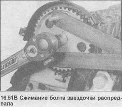
52. Install the gasket, woodruff key and sprocket onto the crankshaft. Temporarily install the timing belt onto the crankshaft, camshaft and water pump sprockets.
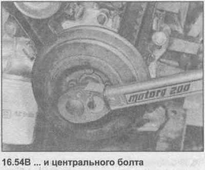
53. Place the crankshaft pulley/vibration damper on the crankshaft sprocket, insert the bolts. Insert the center bolt.
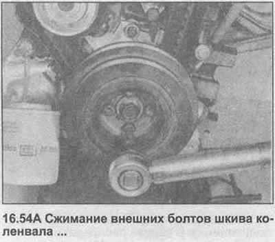
54. Secure the flywheel/drive plate using the method described in Chapter 9, paragraph 12. Tighten the outer bolts first, then the center bolt to the specified tightening torque Specification (photo) Note that the center bolt should be tightened to the initial torque, then tightened to the specified angle.
55. Disconnect the timing belt, align the timing marks on the camshaft sprocket and crankshaft pulley with the indicators on the rear cover. Reinstall the belt without displacing the sprockets and creating some tension by moving the water pump clockwise (photo).
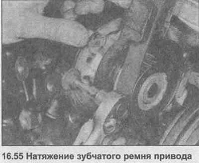
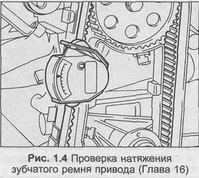
56. Ideally, use the GM recommended tensioning tool (K.M-510-A) to adjust the timing belt tension. If not available, proceed as follows.
57. Turn the water pump clockwise to create moderate belt tension, then tighten the bolts. Turn the crankshaft clockwise one half turn until the belt is tensioned between the crankshaft and camshaft sprockets. Install the tension tool between the camshaft and water pump sprockets, read the readings and compare them with the data in Specifications.
58. If adjustment is necessary, turn the water pump clockwise with the heater to increase tension or counterclockwise to decrease tension. Rotate the crankshaft one full revolution and repeat the test.
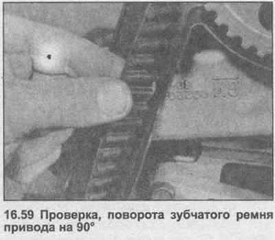
59. If there is no tensioning tool, you can make an approximate adjustment by checking whether it is possible to turn the belt 90° with your thumb and forefinger (photo).
60. After completing the adjustment, tighten the water pump bolts to the specified tightening torque Specification (Section 2), check the alignment of the installation marks.
61. Insert and tighten the bolt securing the water pump drive cover portion to the oil pump housing.
Original posted on the website (OPELBOOK.ru)
62. Install the two timing belt covers.
63. Install the cooling fan pulley. Insert and tighten the screws.
64. Install the camshaft cover with a new plug gasket. Insert and tighten the bolts.
65. On fuel injected models, install the air valve assist hanger to the camshaft housing with a new gasket. Insert and tighten the bolts.
66. Connect the crankcase ventilation hose to the camshaft cover.
67. Insert the engine oil dipstick.
68. Insert and tighten the oil pressure sensor.
69. Using a block, install the new seal into the rear of the camshaft housing. Lubricate the seal lip.
Visitor comments