
Distributor
The ignition distributor is mounted on the end of the camshaft and accordingly driven by it. It performs only the function of distributing high voltage current to the spark plugs. The distributor can be installed in only one position and does not require any adjustments in operation.
Ignition coil
Like a conventional ignition coil, the system ignition coil «Motronic ML4.1» converts the low voltage of the primary circuit into a high voltage of the secondary circuit, necessary for the breakdown of the spark gap between the electrodes of the candles and the ignition of the working mixture.
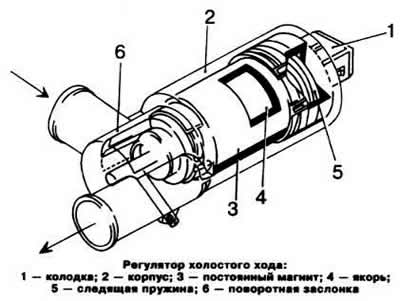
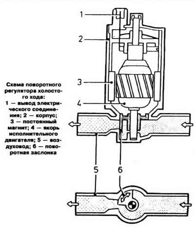
Rotary idle control
The idle speed regulator is located in the bypass air channel, made parallel to the throttle valve, in place of the additional air supply valve. It is a permanent magnet actuator. A damper is installed on the armature shaft, which rotates. overcoming the force of the spring
When the throttle valve is closed, the air channel 8 is blocked to a certain extent by the regulator damper, which ensures the required idling speed of the engine crankshaft.

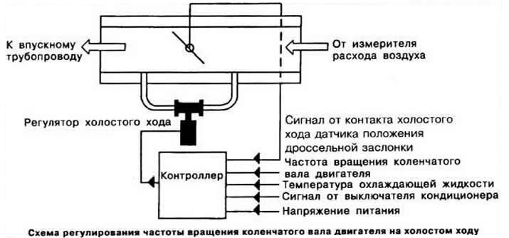
The idle speed controller is controlled by the commands of the controller control units, which determine the degree of opening of the rotary damper depending on the incoming information (see diagram). At the same time, the controller changes the ignition timing accordingly. When the air conditioner is turned on at idle, the controller receives a signal from the air conditioner switch and, on command, the idle speed increases to 1000 rpm. This increases the efficiency of the air conditioner and ensures uninterrupted operation of the engine at idle.
When starting a cold engine and during warm-up, the idle speed controller acts as an additional air supply valve, ensuring that the idle mode is maintained within the specified limits regardless of the engine load.
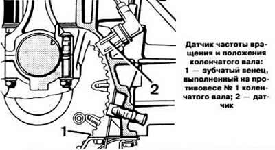
Speed and crankshaft position sensor
The speed and crankshaft position sensor is mounted on the engine block opposite the toothed rim made on the first counterweight of the engine crankshaft. It generates a voltage pulse when a toothed rim passes through its magnetic field.
As the teeth of the rim pass in front of the magnetic sensor, the air gap between the rim and the sensor changes. The changing leakage flux induces a sinusoidal alternating voltage in the sensor winding, the amplitude of which depends on the peripheral speed of the gear rim, the air gap between the rim tooth and the sensor, the shape of the teeth, the magnetic characteristics of the sensor and the mounting bracket.
Depending on the speed of the engine crankshaft, the controller receives voltage pulses of 0.5-100 V from the sensor, which are converted by the input stage of the controller each time the counting circuit is set to zero into rectangular voltage pulses of constant amplitude necessary for the operation of subsequent controller circuits.
The angular gap between the teeth of the rim is 6. The rim is missing one tooth. When a toothless section of the rim passes in front of the sensor, which serves as a marker, the controller receives a pulse of the initial position of the crankshaft.
If the engine does not start or starts with difficulty, then the cause of this may be a malfunction of this sensor.
Controller
The controller processes the information received from the sensors and manages the ignition and fuel injection programs according to its own program.
The controller includes an analog-to-digital converter that converts analog signals from sensors into digital form, a microprocessor, input circuits and output circuits with power amplification stages.
Each engine model corresponds to a certain type of controller. Therefore, when installing a new controller, you must make sure that its marking is identical to the failed device.
Visitor comments