
Removal and installation of the distributor of ignition
Contact the Head Engine electrical equipment.
Removal and installation of the inductive impulse sensor
Contact the Head Engine electrical equipment.
Removal and installation of the injection valve
Presents certain difficulties and is described here briefly.
Engine 2.0 l
1. Disconnect the ground cable from the battery.
2. Remove the parts listed below in the order shown: brake booster vacuum hose, throttle damper and idle air control. Instructions for removing the listed parts are given in the relevant subsections.
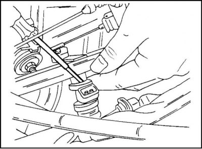
3. Remove the four injection valve clips with a screwdriver as shown in illustration.
4. Remove the fuel distributive highway and its fastening.
5. Remove the injection valves from the fuel distribution line.
When installing:
1. Install injection valves with new seals.
2. Establish fastening and a fuel distributive highway.
3. Other parts are installed in the reverse order of their removal.
Engine 2.4 l
On this engine, the injection valves are removed in pairs.
1. Disconnect the plug connection and disconnect the fuel lines from the fuel distribution line.
2. Remove the fuel distribution line and injection valves. The valves are removed from the line. They are fastened with staples.
Installation is carried out in reverse order.
Throttle Potentiometer Replacement
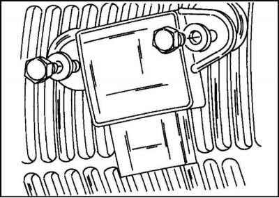
1. On the 2.0L engine, the potentiometer is in the location shown in fig. After disconnecting the plug connection, the potentiometer can be unscrewed. For the 2.4L engine, it is attached with two screws.
Air flow meter replacement
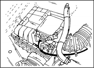
In the considered injection device, instead of an air quantity meter, an air volume meter is used. The meter flap moves according to the amount of intake air. The movement of the damper is converted into a corresponding electrical signal. The location of the 2.0 l engine air volume meter is shown in illustration. below. The 2.4 liter engine has a slightly different meter.
The replacement of the air volume meter is carried out as follows:
1. Disconnect the plug connection and remove the intake air hose. Remove the top of the air filter. If necessary, release the four clips for this.
2. For a 2.0L engine, remove the meter cover and remove the meter itself (4 mounting screws), for a 2.4L engine, remove the gauge from the top of the air filter.
3. Remove the inlet pipeline (engine 2.0 l) and take out the meter.
4. Position the new gauge in the correct position, coat the four screws with threadlocker, and secure the gauge.
5. Install the meter cover, intake elbow, air filter top, air suction hose and plug the plug connection.
Replacing the pressure regulator
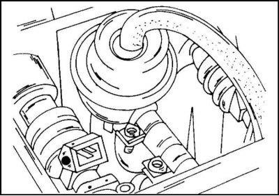
1. The appearance of the pressure regulator for the 2.0 l engine is shown in fig. The 2.4 liter engine has a similar look. The pressure regulator is easily replaced after disconnecting the vacuum and fuel hoses.
Replacing the coolant temperature sensor
1. The sensor is located in the intake manifold and can be turned out after disconnecting the plug connection. In this case, coolant flows out. The sensor is fastened with a torque of 10 Nm.
For a 2.4L engine, disconnect the coolant hose from the intake manifold. The coolant must be drained into a container. The sensor is disconnected after disconnecting the plug connection. Fasten the sensor with a torque of 10 Nm, connect the plug connection and fill the system with fluid.
Replacement of the regulator of idling
The idle speed regulator is a round-shaped part located directly next to the designation "OHC" on the top side of the engine. To replace it, disconnect the plug connection, loosen the clamps, remove the hoses and unscrew the fastening screws.
The sensor is installed in the reverse order of removal.
Visitor comments