


Contents: Throttle potentiometer ⬇ Fuel pressure regulator ⬇ Replacing injection valves…⬇ Replacing the air flow meter ⬇ Replacing the crankshaft TDC sensor ⬇ Replacing the knock sensor ⬇ Oxygen sensor replacement ⬇ Idle speed control valve ⬇ Intake air temperature sensor ⬇ Coolant temperature sensor ⬇
The cable harness connected to the engine has many connectors of different shapes. If more than one plug is disconnected during work, they must be marked accordingly, especially if the plugs are located close to each other.
The following description of some of the works is given in brief form. To carry them out, special knowledge is required. The work on replacing some parts is described.
The injection system works in conjunction with static ignition and a knock sensor. The electronic control unit regulates the mixture composition and ignition.
The amount of fuel injected depends on the duration of opening of the injection valve. The injection duration depends on the engine load (pressure sensor), engine speed (flywheel sensor) and other factors of engine condition.
Throttle potentiometer
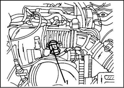
When viewed from the front, the potentiometer (1) is located on the left wall of the engine compartment, to the right of the shock absorber. To remove it, disconnect the plug connection and unscrew the mounting bolts (illustration).
Attach the throttle body before installation. Check that the potentiometer is seated correctly on the throttle shaft. Connect the plug connection.
Fuel pressure regulator
1. The pressure in the fuel system must be relieved in accordance with the above precautions.
2. Disconnect the vacuum hose from the pressure regulator and remove the clamp from the pressure regulator and fuel rail. The pressure regulator is located on the back of the engine.
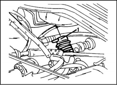
3. Check how the fuel pressure regulator (1) is installed and remove it upwards from the fuel rail as shown in the illustration. The sealing rings are located on the pressure regulator.
4. Before installing the regulator, lubricate the sealing rings with engine oil and insert the regulator into the fuel distribution line so that it takes its original position. Secure the regulator and attach the vacuum hose.
Replacing injection valves (injectors)
1. Relieve the pressure in the system.
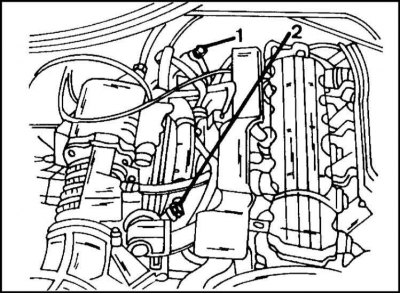
2. Disconnect the fuel lines at locations (1) and (2) as shown in the illustration.
3. Disconnect the acceleration drive at the throttle body. Disconnect the support from the intake manifold and set aside.
4. Disconnect the two vacuum hoses, one from the intake manifold and one from the fuel pressure regulator.
5. Remove the retaining pin from the fuel rail. It is not immediately visible and is located next to the throttle body.
6. Disconnect the plug connection of the injection valves.
7. Unscrew the ground cable nut from the mounting bolt and remove the cable. Loosen the fuel distribution line mounting bolt.
(Article posted on an online resource: «OpelBook»)
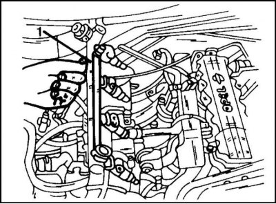
8. Remove the fuel rail (1) together with the injection valves (illustrated). To replace the injection valve, move the clamp away.
Installation is performed in the reverse order of removal. The fuel distribution line is secured with a torque of 8 Nm, the ground cable with a torque of 7 Nm. Reconnect the fuel lines. Secure the throttle support with two bolts.
Replacing the air flow meter
The air flow meter is located directly in front of the air filter and is inserted into the suction hose.
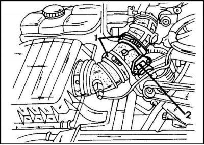
1. Remove the clamps (1) and plug (2) in the illustration.
2. Remove the air flow meter from the suction hose. If there is any external damage, it should be replaced. The meter has an arrow indicating the direction of air flow. The hoses must be connected tightly.
Replacing the crankshaft TDC sensor
Contact the Head Engine electrical equipment.
Replacing the knock sensor
Contact the Head Engine electrical equipment.
Oxygen sensor replacement
1. The oxygen sensor is located in the exhaust pipe and can be removed after disconnecting the plug (at the gearbox) connections. Before installing the sensor, the connecting thread must be lubricated with a special lubricant. The sensor is tightened with a torque of 30 Nm. Make sure that the sensor wires do not come into contact with the exhaust pipe and cannot rub against the vehicle chassis elements.
Idle speed control valve
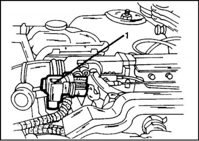
1. The idle speed control valve (1) is located in the location shown in the illustration on the throttle body and is secured with two bolts. Before removing, disconnect the plug connection. The regulator has a seal that must be installed correctly.
Intake air temperature sensor
1. The sensor is screwed into the intake air hose near the inlet to the air filter.
After disconnecting the plug connection and removing the intake air hose, the sensor can be pressed out with a sharp object (for example, with a knife) from the hose. Before installing the sensor in place, check the condition of the hose. Reinstall all removed parts.
Coolant temperature sensor
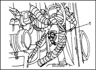
1. Replacing this sensor is quite labor-intensive, since access to it is not convenient. It is screwed into the thermostat housing (illustration). To get to the sensor (1), it is necessary to remove the V-belt and the generator (move aside), disconnect the plug connections on the air intake hose, the air intake hose between the air filter housing and the throttle body and the temperature sensor. After this, unscrew the sensor. The new sensor is secured with a torque of 8 Nm. The removed parts are installed in the reverse order.
Visitor comments