
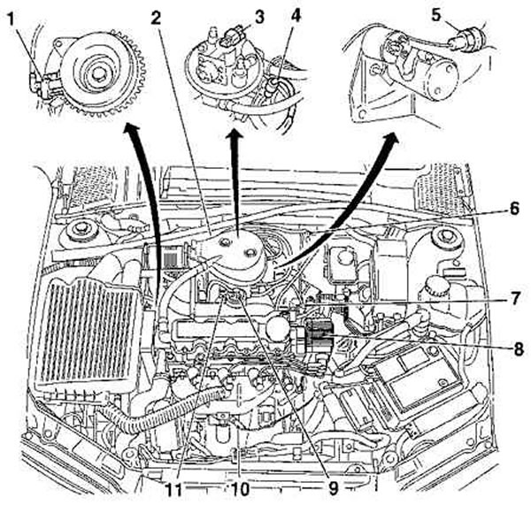
1. Crankshaft position sensor
2. Throttle body
3. Fuel injectors
4. Throttle potentiometer
5. Knock sensor
6. MAP sensor
7. Evaporative Emission System
8. Ignition block
9. Exhaust gas re-burning system
10. Oxygen sensor
11. Idle speed control stepper motor
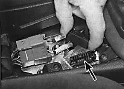
Location of the diagnostic connector of the fuel injection system
Removing the trim in front of the handbrake lever
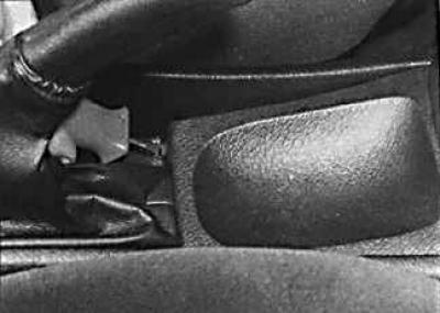
To access the diagnostic socket, you must remove the trim from the top of the center console.
The Multec system is a combined ignition and fuel injection system, and includes a catalyst, an evaporative emission control system and an exhaust gas reburning system.
The fuel pump, immersed in the fuel tank, delivers fuel from the tank to the fuel injector through the filter. The fuel pressure in the system is controlled by a pressure regulator. The regulator allows excess fuel to return to the fuel tank when the pressure in the fuel system is exceeded.
The electrical control system consists of an ECU together with the following sensors:
- the throttle potentiometer tells the ECU whether the throttle is open or closed;
- the coolant temperature sensor tells the ECU the engine temperature;
- the oxygen sensor informs the ECU of the oxygen content in the exhaust gases;
- the crankshaft position sensor tells the ECU the engine speed and crankshaft position;
- a knock sensor installed in the cylinder block is used to detect the onset of detonation or early ignition;
- the manifold absolute pressure sensor tells the ECU the vacuum in the intake manifold;
- the ABS unit sensor tells the ECU the relative vehicle speed;
- The air conditioning compressor switch tells the ECU to turn on the air conditioning system.
All information from the sensors is analyzed by the ECU, and on this basis, the unit determines the appropriate ignition timing and composition of the fuel mixture. The unit controls the fuel injector by changing the pulse width, that is, the amount of time the injector is open, to provide a richer or leaner fuel mixture.
The ECU also controls idle speed. To do this, there is a stepper motor that controls the position of the throttle.
The ECU also controls the composition of the exhaust gases and the fuel vapor control system.
If there is an error in any of the data received from the sensors, the ECU enters standby mode. In this case, the ECU ignores the incorrect sensor signal and assumes a pre-programmed value that allows the engine to continue running, albeit with less efficiency. If the ECU enters the backup mode, then the alarm lamp on the instrument cluster will light up and the damage will be recorded in the ECU memory. After that, it is necessary to carry out a full test of the engine management system using a special electronic diagnostic test stand, which is simply plugged into the diagnostic socket of the system. The connector is located behind the center console. At the same time, to access it, it is necessary to remove the decorative trim in front of the handbrake lever.
Visitor comments