
OpelBook.ru
Cars AvtoVAZ Cars Mitsubishi Cars BMW Cars Mercedes Cars Nissan Cars Toyota Cars Chevrolet
English Русский
Български
Беларускі
Український
Српски
Hrvatski
Română
Polski
Slovenský
Magyar
 |  Sitemap  |  Contacts  |    


Main Astra Corsa Insignia Kadett Omega Vectra Zafira Others Articles
Omega A (1986-1993) Omega B (1993-1999) Omega B2 (1999-2003)
  • Main
  • Omega
  • Omega B
  • Power unit
  • Power system (petrol)
  • Fuel injection system (2.0 liter engine)

Fuel injection system (2.0 liter engine) (Opel Omega B)

            0

Contents: Fuel injectors ⬇ Fuel pressure regulator ⬇ Idle speed control valve ⬇ Throttle potentiometer ⬇ Coolant temperature sensor ⬇ SOHC engine ⬇ Dohc engine ⬇ Incoming air temperature sensor ⬇ Air flow sensor ⬇ Crankshaft position sensor ⬇ Fuel knock sensor ⬇ Camshaft Position Sensor - DOHC…⬇ Electronic control unit ⬇ Fuel injection system relay ⬇ Switch in the air conditioning system ⬇

Fuel injectors


Removal and installation


SOHC Engine

1. Release the pressure from the fuel system and disconnect the negative battery cable.

2. Remove the fuel manifold.

3. Remove the retaining clip and remove the corresponding injector.

4. Installation is carried out in the reverse order of removal.

DOHC Engine

5. Release the pressure from the fuel system and disconnect the negative battery cable.
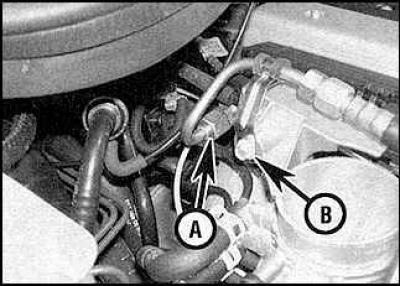
5. Release the pressure from the fuel system and disconnect the negative battery cable.


6. Loosen the nut (A) and bolt (B) connecting the fuel supply pipe.
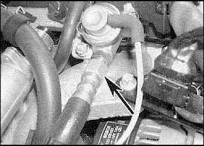
6. Loosen the nut (A) and bolt (B) connecting the fuel supply pipe.


7. Loosen the return pipe connection nut and disconnect the fuel pipes from the fuel manifold.


8. Remove the fuel rail and injectors.

9. Remove the retaining clip and remove the corresponding injector. Remove the sealing ring.

10. Installation is carried out in the reverse order of removal.

Fuel pressure regulator


Removal and installation


1. Release the pressure from the fuel system and disconnect the negative battery cable.
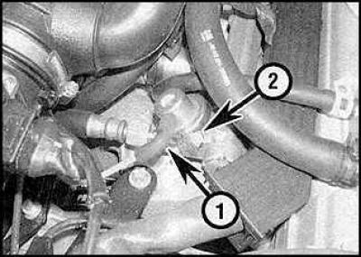
1. Release the pressure from the fuel system and disconnect the negative battery cable.


2. Disconnect the vacuum hose (1) and the mounting clamp (2) of the fuel pressure regulator.

3. Loosen the mounting clamp and remove the regulator.

4. Installation is carried out in the reverse order of removal.

Idle speed control valve


Removal and installation


1. Remove the air intake pipe.

2. Disconnect the connection connector, unscrew the mounting screws and remove the valve.

3. Installation is carried out in the reverse order of removal.

Throttle potentiometer


Removal and installation
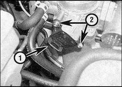


Removal and installation


1. Disconnect the connection connector (1). Unscrew the mounting screws (2) and remove the potentiometer.


2. Installation is carried out in the reverse order of removal.

Coolant temperature sensor


Removal and installation


SOHC engine


See. subsection 4.7.

Dohc engine


See. subsection 4.7.

Incoming air temperature sensor


Removal and installation
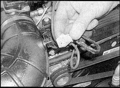


Removal and installation


1. Disconnect the connection connector.
1. Disconnect the connection connector.


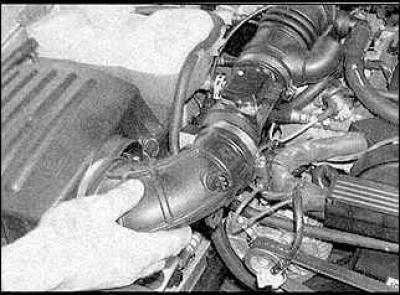
2. Loosen the mounting clamps and remove the air intake pipe.

3. Remove the sensor.

4. Installation is carried out in the reverse order of removal.

Air flow sensor


Removal and installation
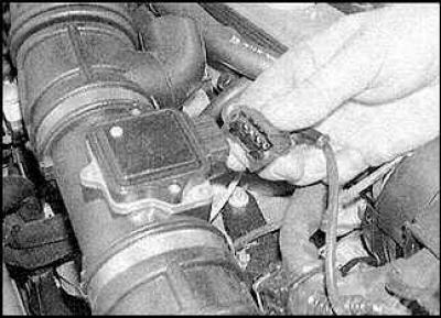


Removal and installation


1. Disconnect the sensor connection connector. Remove the air intake pipe.


1. Disconnect the sensor connection connector. Remove the air intake pipe.


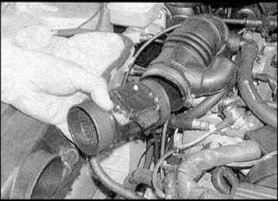
2. Loosen the mounting clamp and remove the sensor.

3. Installation is carried out in the reverse order of removal.

Crankshaft position sensor


Removal and installation


SOHC Engine

1. Remove the front timing belt cover.

2. On models with air conditioning, remove the left engine/transmission mount and mounting bracket from the cylinder block.

3. Disconnect the sensor connection connector.

4. Loosen the mounting bolt and remove the sensor.

5. Installation is carried out in the reverse order of removal.

DOHC Engine
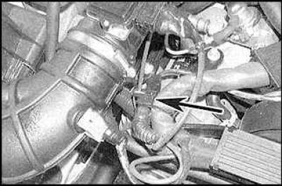
DOHC Engine


6. The sensor is located on the left side of the cylinder block, under the power steering pump. To remove the sensor (indicated by the arrow) disconnect the connection connector. Unscrew the mounting bolt and remove the sensor.


7. Installation is carried out in the reverse order of removal.

Fuel knock sensor


Removal and installation


SOHC Engine

1. The sensor is located on the right side of the cylinder block. Disconnect the connection connector, unscrew the mounting bolt and remove the sensor.

2. Installation is carried out in the reverse order of removal.

DOHC Engine

3. The sensor is located on the right side of the cylinder block. Remove the starter if necessary for better access.

4. Disconnect the connection connector, unscrew the mounting bolt and remove the sensor.

5. Installation is carried out in the reverse order of removal.

Camshaft Position Sensor - DOHC Engine


Removal and installation


1. Remove the spark plug housing.

2. Disconnect the sensor connection connector.

[Original article on the web portal: www.opelbook.ru]

3. Remove the front timing belt cover.

4. Loosen the mounting bolt and remove the sensor.

5. Installation is carried out in the reverse order of removal.

Electronic control unit


Removal and installation


1. Disconnect the negative battery cable and remove the relay box cover in the engine compartment.
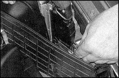
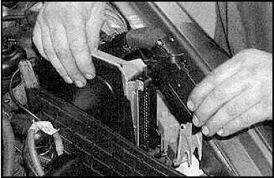
1. Disconnect the negative battery cable and remove the relay box cover in the engine compartment.


1. Disconnect the negative battery cable and remove the relay box cover in the engine compartment.


2. Remove the electronic control unit from the socket and disconnect the connection connector.


3. Installation is carried out in the reverse order of removal.

Fuel injection system relay


Removal and installation
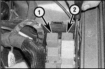


Removal and installation


1. Remove the engine compartment relay box cover. The fuel pump relay (1) and the fuel injection system relay (2) are located in the engine compartment relay box.
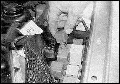
1. Remove the engine compartment relay box cover. The fuel pump relay (1) and the fuel injection…


2. Replace the corresponding relay.

Switch in the air conditioning system


Removal and installation


To replace the switch, you need to contact a specialist.


This article is available at russian, bulgarian, belarusian, ukrainian, serbian, croatian, romanian, polish, slovak, hungarian
Checking the article: Fedorova Varvara

Share information:

Previous articles
Opel Omega B: Power system (petrol)
Next articles

Throttle body
Fuel tank — removal and installation
Fuel level sensor — removal and installation
Fuel pump — removal and installation
Releasing pressure from the fuel injection system
Accelerator pedal — removal and installation
Fuel injection system (2.5 and 3.0 liter engines)
Intake manifold — removal and installation
Exhaust manifold — removal and installation
Multi-flow air supply system
Exhaust gas system


See similar ones from other Opel car manuals:
▶ General information about the fuel injection system of a… Opel Corsa B (1993-2000)
▶ Single-point fuel injection system of the SOCH 1.6L engine Opel Vectra B (1995-2002)
▶ Fuel injection system Bosch M1.5.4 for DOHC engine Opel Frontera A (1991-1998, petrol)
▶ Multec Single Point Fuel Injection System Components —… Opel Astra F (1991-1998, petrol)
▶ Fuel system of a carburetor engine Opel Kadett E (1984-1995)
Link to this page in different formats

Visitor comments


No comments yet


How much will 33 + 39 =


Omega B2 (1999-2003) 
  • General information
  • User manual
  • Maintenance
  • Troubleshooting
  • Power unit
  • Petrol 4-cylinder
  • Petrol 6-cylinder
  • Engine overhaul
  • Diesel engines 2.0 l
  • Diesel engines 2.5 l
  • Cooling and heating
  • Injection system (gasoline)
  • Fuel system (diesel)
  • Fuel system
  • Exhaust system
  • Ignition system
  • Transmission
  • Clutch
  • Mechanical gearbox
  • Automatic gearbox
  • Main gear and shafts
  • Chassis
  • Brake system
  • Car suspension
  • Steering
  • Body
  • Body elements
  • Electrical equipment
  • Equipment and devices
  • Electrical circuits
Omega B (1993-1999) 
  • General information
  • User manual
  • Tips for the car owner
  • Maintenance (gasoline)
  • Maintenance (diesel)
  • Power unit
  • Petrol engine SOHC 2.0 l
  • Petrol engine DOHC 2.0 l
  • Petrol engines 2.5 and 3.0 l
  • Repair of gasoline engines
  • Diesel engine 2.0 l
  • Diesel engine repair 2.0 l
  • Diesel engine 2.5 l
  • Cooling and heating
  • Power system (petrol)
  • Emission reduction
  • Fuel system (diesel 2.0 l)
  • Fuel system (diesel 2.5 l)
  • Launch system
  • Ignition system
  • Transmission
  • Clutch
  • Mechanical gearbox
  • Automatic gearbox
  • Drive shafts
  • Chassis
  • Brake system
  • Wheel suspension
  • Steering
  • Body
  • Exterior
  • Interior
  • Doors and windows
  • Electrical equipment
  • Equipment and devices
  • Wiring diagrams (early)
  • Wiring diagrams (late)
Omega A (1986-1993) 
  • General information
  • User manual
  • Maintenance
  • Changes and additions
  • Troubleshooting
  • Power unit
  • Gasoline engines
  • Diesel engines
  • Cooling system
  • Fuel system (gasoline)
  • Fuel system (diesel)
  • Ignition system
  • Transmission
  • Clutch
  • Mechanical gearbox
  • Automatic gearbox
  • Cardan shaft
  • Drive shafts
  • Chassis
  • Brake system
  • Car suspension
  • Steering
  • Body
  • Exterior
  • Interior
  • Electrical equipment
  • Power devices
  • Lighting and appliances
  • Electrical circuits
OpelBook.ru © 2017–2026 · Mobile version · · Sitemap: EN BG BY UA RS HR RO PL SK HU · Feedback · Site search
Astra F, petrol · Astra G, petrol · Astra G · Astra H · Astra J, petrol · Corsa B · Corsa C, petrol · Corsa C · Insignia A · Kadett D · Kadett E · Omega A · Omega B · Omega B2 · Vectra A, petrol · Vectra A · Vectra B, petrol · Vectra B · Vectra C · Zafira A, petrol · Frontera A, petrol · Frontera B · Ascona C · Vivaro A ·
We want your visit to be comfortable 🤝! We use cookies 🍪 to make that happen.