
Fuel injectors
Removal and installation
1. Remove the lower section of the intake manifold.
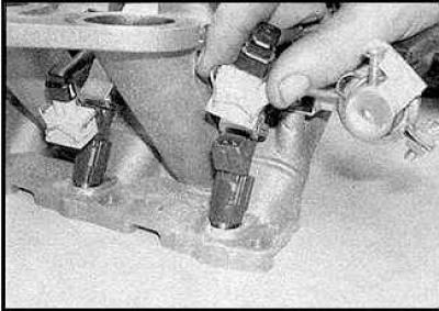
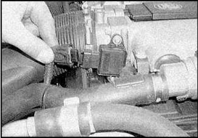
2. Disconnect the connectors from the injectors.
3. Remove the wiring harness cover.
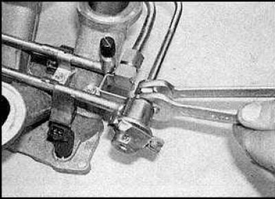
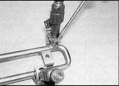
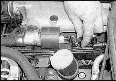
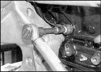
4. Loosen the fuel pipe nuts.
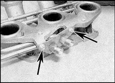
5. Loosen the fixing screws (indicated by arrows).
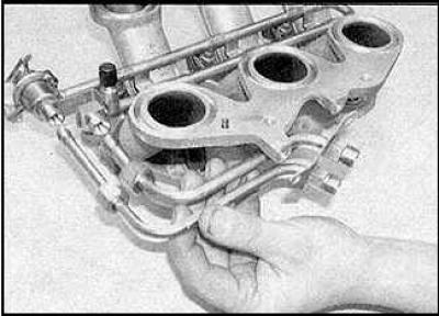
6. Remove fuel pipes.
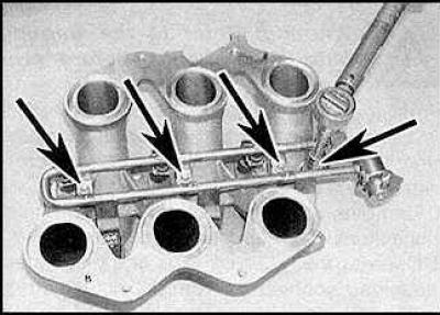
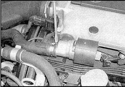
7. Loosen the fixing screws (indicated by arrows) fuel manifold.

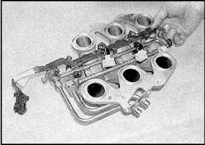
8. Remove the fuel manifold along with the injectors.
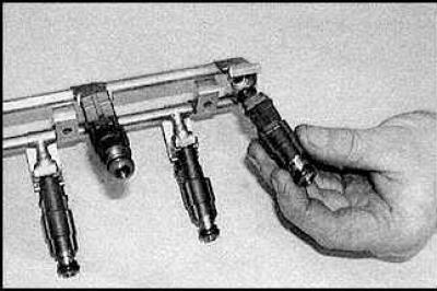
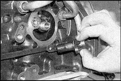
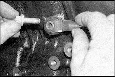
9. Remove the appropriate mounting clip (drawing on the left) and remove the injector (drawing on the right).
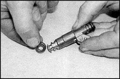
10. Installation is carried out in the reverse order of removal. Replace o-rings.
Fuel pressure control
Removal and installation
1. Release pressure from the power system and disconnect the negative battery cable.
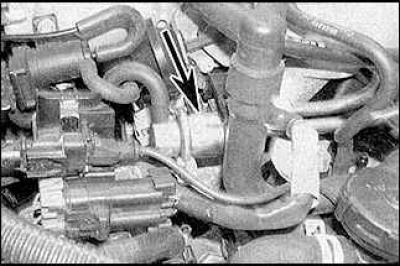
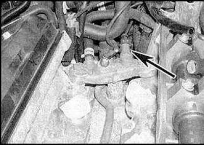
2. Remove the wiper arms and drain panel. Fuel pressure control (indicated by an arrow) located behind the intake manifold.
3. Disconnect the vacuum hose from the regulator.
4. Loosen the clamp and remove the regulator.
5. Installation is carried out in the reverse order of removal.
Idle speed control valve
Removal and installation
1. Disconnect the valve connector.
2. Disconnect the hose from the valve and remove the valve.
3. Installation is carried out in the reverse order of removal.
Throttle Potentiometer
Removal and installation
1. Disconnect the connector. Loosen the fixing screws and remove the potentiometer.
2. Installation is carried out in the reverse order of removal.
Coolant temperature sensor
Location of coolant temperature sensor
coolant temperature sensor (indicated by an arrow) located in the outlet (The picture shows the intake manifold removed).
Removal and installation
See subsection 4.7.
Intake air temperature sensor
Removal and installation
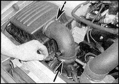
1. Disconnect the connection connector, release the fixing clamps (indicated by arrows). Remove the air intake pipe.
2. Remove the sensor.
3. Installation is carried out in the reverse order of removal.
Air flow sensor
Removal and installation
1. Disconnect the sensor connector. Remove the air intake pipe.
2. Loosen the clamp and remove the sensor.
3. Installation is carried out in the reverse order of removal.
Crankshaft position sensor
The sensor is located on the left side of the cylinder block, under the oil filter.
Removal and installation
1. Remove the wiper arms and drain panel.

2. Disconnect the connector (indicated by an arrow) crankshaft position sensor, which is attached to the rear engine bracket.
3. Loosen the mounting bolt and remove the sensor.
4. Installation is carried out in the reverse order of removal.
Fuel knock sensor in the right row of cylinders
Removal and installation
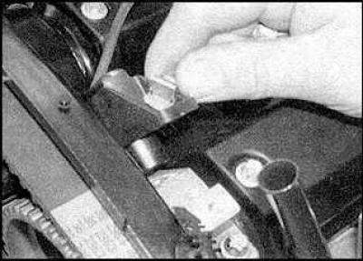
1. Remove the drive belt tensioner. Remove the generator.
2. Disconnect the sensor connector.
3. Loosen the mounting bolt and remove the sensor.
4. Installation is carried out in the reverse order of removal.
Fuel knock sensor in the left bank of cylinders
Removal and installation
1. On A/C models, remove the left engine/transmission mount and mounting bracket from the cylinder block.
2. Disconnect the sensor connector.
3. Loosen the mounting bolt and remove the sensor.
4. Installation is carried out in the reverse order of removal. Tighten the sensor mounting bolt to the required tightening torque.
Camshaft position sensor
Removal and installation
1. Disconnect the sensor connector.
2. Loosen the mounting bolt and remove the sensor.
3. Installation is carried out in the reverse order of removal.
Electronic control unit
Removal and installation
See subsection 5.1.12.1.
Fuel injection relay
Removal and installation
See subsection 5.1.12.1.
Switch in the air conditioning system
Removal and installation
To replace the switch, you must contact a specialist.
Visitor comments