
OpelBook.ru
Cars AvtoVAZ Cars Mitsubishi Cars BMW Cars Mercedes Cars Nissan Cars Toyota Cars Chevrolet
English Русский
Български
Беларускі
Український
Српски
Hrvatski
Română
Polski
Slovenský
Magyar
 |  Sitemap  |  Contacts  |    


Main Astra Corsa Insignia Kadett Omega Vectra Zafira Others Articles
Vectra A (1988-1995, petrol) Vectra A (1988-1995) Vectra B (1995-2002, petrol) Vectra B (1995-2002) Vectra C (2002-2008)
  • Main
  • Vectra
  • Vectra B
  • Power unit
  • Fuel system (gasoline)
  • Elements of the multi-point fuel injection system of the 1.6 l engine

Elements of the multi-point fuel injection system of the 1.6 l engine (Opel Vectra B)

            0

Contents: Fuel line and injectors ⬇ Pressure regulator ⬇ Idle speed control motor ⬇ Throttle potentiometer ⬇ Coolant temperature sensor ⬇ Engine Air Intake Temperature Sensor ⬇ Manifold Absolute Pressure Sensor ⬇ Crankshaft sensor ⬇ Camshaft sensor ⬇ Knock sensor ⬇ Electronic control device ⬇ Fuel pump relay ⬇

Fuel line and injectors


Removal and installation


1. Relieve pressure in the fuel system. Remove the ground wire from the battery.

2. Remove the upper section of the intake manifold.

3. Disconnect the electrical connectors from the four fuel injectors and remove the wiring harness from the fuel line.

4. Unscrew the union nuts and disconnect the fuel hoses from the fuel line.

5. Remove the three bolts and remove the fuel line and injectors from the intake manifold. Remove the lower sealing rings from the fuel injectors.

6. Release the retaining clips and remove the fuel injectors from the fuel line. Remove the upper O-rings from the fuel injectors.

7. Installation is performed in the reverse order of removal. In this case, new sealing rings must be installed on the fuel injectors.

Pressure regulator


Removal and installation


1. Relieve the pressure in the fuel system and remove the ground cable from the battery.

Material copied from the portal: www.OpelBook.ru
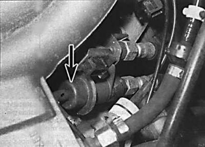
1. Relieve the pressure in the fuel system and remove the ground cable from the battery.


2. To improve access to the fuel rail, remove the harness bracket from the intake manifold. On 1.6L DOCH engines, the pressure regulator is located on the left front end of the fuel rail.


3. While holding the regulator with a wrench, unscrew the fuel supply hose union nut. Disconnect the fuel supply hose and vacuum hose from the regulator.

4. Remove the bolts and remove the electrical wire bracket from the fuel line.

5. Remove the regulator from the end of the fuel line together with the sealing ring.

6. Installation is performed in the reverse order of removal. In this case, it is necessary to use a new sealing ring.

Idle speed control motor


Removal and installation


1. To access the idle speed control motor, remove the throttle body.
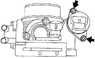
1. To access the idle speed control motor, remove the throttle body.


2. Unscrew the screws (indicated by arrows) and remove the idle speed control motor together with the sealing rings.
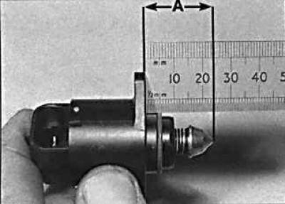
2. Unscrew the screws (indicated by arrows) and remove the idle speed control motor together with…


3. Installation is performed in the reverse order of removal. Before installing the engine, check that the plunger end protrudes from the engine body by no more than 33 mm.


Throttle potentiometer


Removal and installation


1. Remove the throttle body.
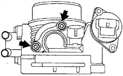
1. Remove the throttle body.


2. Unscrew the screws (indicated by arrows) and remove the potentiometer from the throttle.

3. When installing the potentiometer, make sure it is properly aligned with the throttle shaft.

Coolant temperature sensor


The coolant temperature sensor is screwed into the thermostat housing.

Engine Air Intake Temperature Sensor


The temperature sensor is installed in the intake duct that connects the air filter housing to the intake manifold.

Removal and installation


1. Turn off the ignition and disconnect the electrical connector from the sensor.

2. Remove the sensor and remove the sealing ring from the intake port.

3. Installation is carried out in the reverse order of removal.

Manifold Absolute Pressure Sensor
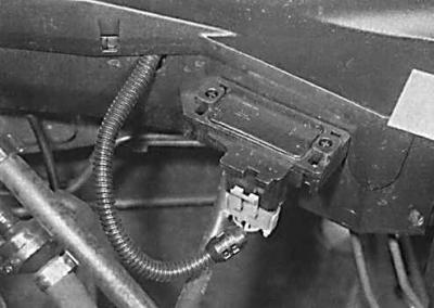


Manifold Absolute Pressure Sensor


The absolute pressure sensor in the intake manifold is installed on the bulkhead of the engine compartment on the left side of the intake manifold.


Removal and installation


1. Turn off the ignition and remove the electrical connector and vacuum hose from the sensor. Remove the sensor.

2. Installation is carried out in the reverse order of removal.

Crankshaft sensor


The sensor is mounted on the rear of the cylinder block and is accessible from underneath the vehicle.

Removal and installation


1. Raise the front of the vehicle and support it on stands.

2. Remove the sensor electrical wiring from the mounting brackets and disconnect the sensor electrical connector.

3. Unscrew the bolt and remove the sensor.

4. Installation is carried out in the reverse order of removal.

5. Using a feeler gauge blade, check that the gap between the end of the sensor and the teeth of the crankshaft pulley is 1±0.7 mm.

Camshaft sensor


1. Remove the upper timing belt cover.

2. Release the sensor wiring from the mounting brackets and disconnect the electrical connector.
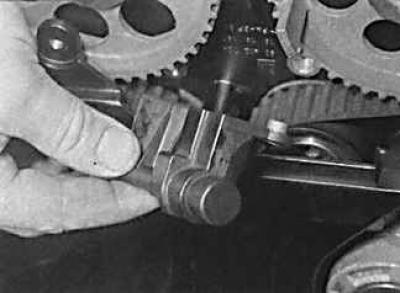
2. Release the sensor wiring from the mounting brackets and disconnect the electrical connector.


3. Unscrew the bolts and remove the sensor from the cylinder head.

4. Installation is carried out in the reverse order of removal.

Knock sensor


The knock sensor is mounted on the rear of the cylinder block and is accessible from underneath the vehicle.


Removal and installation


1. Raise the front of the vehicle and support it on stands.

2. Disconnect the sensor electrical connector located on the sensor wires.

3. Unscrew the bolt and remove the sensor from the engine.

4. Check that the mating surfaces of the sensor and the cylinder block are clean and dry, install the sensor, secure it with a bolt and connect the electrical connector.

Electronic control device


The ECU is located under the water deflector in front of the windshield.

Removal and installation


1. Remove the ground cable from the battery. Remove the wiper arms.

2. Remove the upper seal from the engine compartment bulkhead and remove the water deflector.

3. Unscrew the nuts and remove the protective cover of the ECU unit.

4. Disconnect the electrical connectors, unscrew the nuts and remove the ECU unit.

5. Installation is carried out in the reverse order of removal.

Fuel pump relay


The fuel pump relay is located in the engine compartment in the relay block.

Removal and installation


1. Remove the relay box cover and remove the fuel pump relay which is colored purple.

2. Installation is carried out in the reverse order of removal.


This article is available at russian, bulgarian, belarusian, ukrainian, serbian, croatian, romanian, polish, slovak, hungarian
Checking the article: Pavlovsky Nikolay

Share information:

Previous articles
Opel Vectra B: Fuel system (gasoline)
Next articles

Elements of a single-point fuel injection system
Checking the fuel injection system
Throttle body — removal and installation
Fuel tank — removal and installation
Fuel level sensor — removal and installation
Fuel pump — removal and installation
Elements of the multi-point fuel injection system of 1.8 and 2.0 l engines
Intake manifold — removal and installation
Exhaust manifold — removal and installation
Exhaust gas system


See similar ones from other Opel car manuals:
▶ Multec Multi-Point Fuel Injection System Components —… Opel Astra F (1991-1998, petrol)
▶ General information about the fuel injection system of a… Opel Corsa B (1993-2000)
▶ Fuel injection system (2.0 liter engine) Opel Omega B (1993-1999)
▶ Fuel injection system Bosch M1.5.4 for DOHC engine Opel Frontera A (1991-1998, petrol)
▶ Fuel system of a carburetor engine Opel Kadett E (1984-1995)
Link to this page in different formats

Visitor comments


No comments yet


How much will 34 + 33 =


Vectra C (2002-2008) 
  • General information
  • User manual
  • Vehicle device
  • Maintenance
  • Troubleshooting
  • Power unit
  • Engine repair
  • Cooling system
  • Power and control system
  • Engine electrics
  • Transmission
  • Clutch
  • Car gearbox
  • Drive shafts
  • Chassis
  • Car suspension
  • Steering
  • Brake system
  • Body
  • Exterior
  • Interior
  • Doors, locks and windows
  • Heating and ventilation
  • Electrical equipment
  • Equipment and devices
  • Headlights and lighting
  • Electrical circuits
Vectra B (1995-2002) 
  • General information
  • User manual
  • Weekly checks
  • Maintenance (gasoline)
  • Maintenance (diesel)
  • Troubleshooting
  • Power unit
  • SOHC gasoline engine
  • DOHC petrol engine
  • Diesel engine 1.7 liter
  • Diesel engine 2.0 liters
  • Engine repair
  • Cooling system
  • Fuel system (gasoline)
  • Fuel system (diesel)
  • Charging system
  • Launch system
  • Ignition and preheat
  • Transmission
  • Clutch
  • Mechanical gearbox
  • Automatic gearbox
  • Drive shafts
  • Chassis
  • Brake system
  • Wheel suspension
  • Steering
  • Body
  • Exterior
  • Interior
  • Doors and windows
  • Heating and ventilation
  • Electrical equipment
  • Equipment and devices
  • Electrical circuits
Vectra B (1995-2002, petrol) 
  • General information
  • Maintenance
  • Help with malfunctions
  • Power unit
  • Engine repair
  • Exhaust system
  • Cooling system
  • Fuel system
  • Multec injection system
  • Four point injection
  • Transmission
  • Clutch
  • Gearbox and drive
  • Chassis
  • Wheel suspension
  • Steering
  • Brake system
  • Wheels and tires
  • Body
  • Exterior
  • Interior
  • Electrical equipment
  • Fuses and electronics
  • Power devices
  • Ignition system
  • Lighting and signaling
  • Equipment and devices
  • Heating and ventilation
  • Electrical circuits
Vectra A (1988-1995) 
  • Power unit
  • Engine repair
  • Ignition system
  • Lubrication system
  • Cooling system
  • Injection system
  • Fuel system (carburetor)
  • Fuel system (diesel)
  • Exhaust system
  • Transmission
  • Clutch
  • Car gearbox
  • Chassis
  • Front suspension
  • Rear suspension
  • Steering
  • Brake system
  • Wheels and tires
  • Body
  • Exterior
  • Interior
  • Electrical equipment
  • Electrical circuits
Vectra A (1988-1995, petrol) 
  • General information
  • User manual
  • Maintenance
  • Power unit
  • SOHC engine
  • DOHC engine
  • Cooling and ventilation
  • Fuel system (carburetor)
  • Fuel system (injector)
  • Exhaust converter
  • Transmission
  • Clutch
  • Mechanical gearbox
  • Automatic gearbox
  • Drive shafts
  • Chassis
  • Brake system
  • Car suspension
  • Steering
  • Body
  • Body elements
  • Electrical equipment
  • Power devices
  • Equipment and devices
  • Electrical circuits
OpelBook.ru © 2017–2026 · Mobile version · · Sitemap: EN BG BY UA RS HR RO PL SK HU · Feedback · Site search
Astra F, petrol · Astra G, petrol · Astra G · Astra H · Astra J, petrol · Corsa B · Corsa C, petrol · Corsa C · Insignia A · Kadett D · Kadett E · Omega A · Omega B · Omega B2 · Vectra A, petrol · Vectra A · Vectra B, petrol · Vectra B · Vectra C · Zafira A, petrol · Frontera A, petrol · Frontera B · Ascona C · Vivaro A ·
We want your visit to be comfortable 🤝! We use cookies 🍪 to make that happen.