


Contents: Fuel injector ⬇ Pressure regulator ⬇ Idle speed control motor ⬇ Throttle potentiometer ⬇ Coolant temperature sensor ⬇ Manifold Absolute Pressure Sensor ⬇ Crankshaft sensor ⬇ Knock sensor ⬇ Electronic control unit (ecu) ⬇ Fuel pump relay ⬇
Fuel injector
The fuel injector, centrally mounted in the throttle body, is an electromagnetic valve that supplies a certain dose of fuel for the corresponding engine load mode. This dose of fuel in the form of finely atomized particles is sent directly to the intake manifold. At the same time, the injector is under constant fuel pressure, which is provided by the fuel pump and maintained by the pressure regulator.
Removal and installation
1. Relieve the pressure in the fuel system and remove the ground cable from the battery.
2. Loosen the clamp and remove the air intake pipe from the throttle body housing. Disconnect the hoses, unscrew the screws and remove the upper throttle body housing.
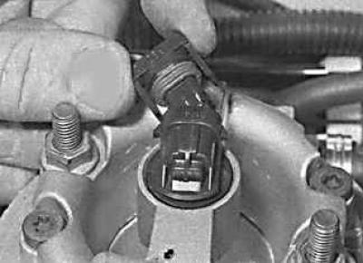
3. Release the retaining clips and disconnect the electrical connector from the fuel injector.
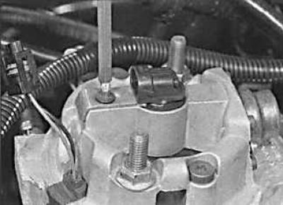
4. Remove the screw securing the plate that holds the fuel injector.
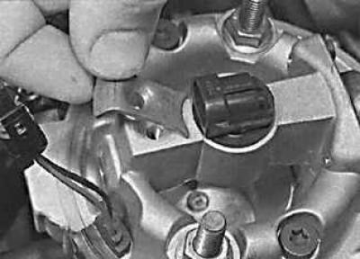
5. Remove the fuel injector mounting plate.
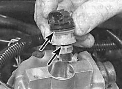
6. Remove the fuel injector from the throttle body along with the sealing rings (indicated by arrows).
7. Installation is performed in the reverse order of removal. In this case, new sealing rings must be installed on the fuel injector.
Pressure regulator
Warning! The pressure regulator is an integral part of the upper section of the throttle body.
Removal and installation
1. Relieve the pressure in the fuel system and remove the ground cable from the battery.
2. Loosen the clamp and disconnect the air intake pipe from the upper throttle body housing. Disconnect the hoses, unscrew the screws and remove the upper throttle body housing.
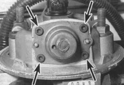
3. Using a marker, make alignment marks on the governor cover and throttle body. Then remove the screws (indicated by arrows) and remove the pressure regulator cover.
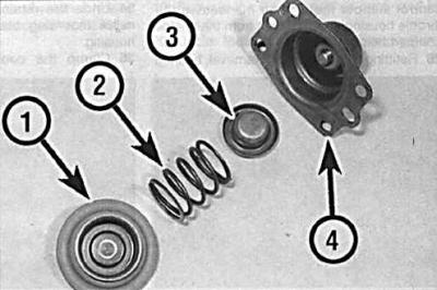
4. Remove the cover (4), then remove the spring seat (3), spring (2) and diaphragm (1). Check the condition of the diaphragm and replace it if necessary.
5. Installation is carried out in the reverse order of removal.
Idle speed control motor
Removal and installation
1. Remove the ground cable from the battery.
2. To improve access to the engine, loosen the clamp and disconnect the air intake pipe from the upper throttle body housing. Disconnect the hoses, unscrew the screws and remove the upper throttle body housing.
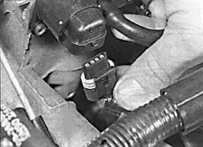
3. Loosen the fasteners and disconnect the electrical connectors from the idle speed control stepper motor, which is mounted to the front of the throttle body.
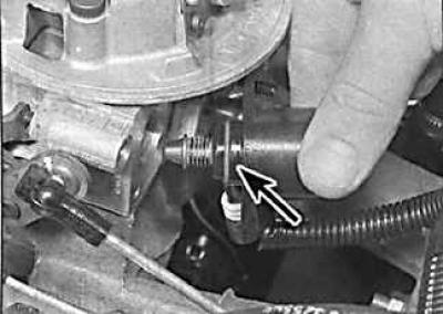
4. Remove the screws and idle speed control motor (indicated by the arrow).
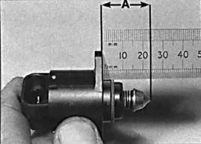
5. Installation is performed in the reverse order of removal. In this case, it is necessary to install a new sealing ring. Also check that the plunger end does not protrude more than 28 mm from the engine. If necessary, move the plunger to set its correct protrusion.
(Text copied from an internet website OPELBOOK)
Throttle potentiometer
Removal and installation
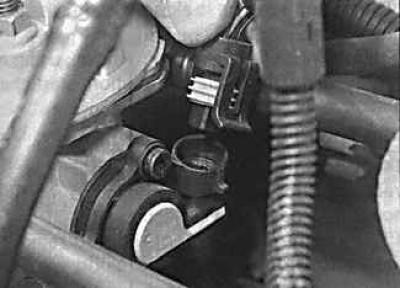
1. Remove the ground cable from the battery. Loosen the clamps and remove the electrical connector from the throttle potentiometer, which is mounted on the left side of the throttle body.
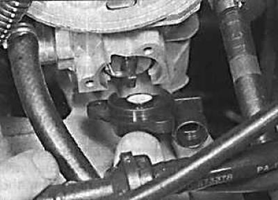
2. Unscrew the screws and remove the potentiometer.
3. Before installation, apply a product to the threads of the bolts to prevent them from loosening, install the potentiometer and secure with bolts, tightening them to the required torque.
Coolant temperature sensor
The coolant temperature sensor is mounted at the rear of the intake manifold.
Manifold Absolute Pressure Sensor
The absolute pressure sensor in the intake manifold is installed on the bulkhead of the engine compartment to the left of the throttle body.
Removal
Turn off the ignition, disconnect the electrical connector and vacuum hose from the sensor. Unscrew and remove the sensor.
Crankshaft sensor
The sensor is mounted on the rear of the cylinder block and is accessible from underneath the vehicle.
Removal and installation
1. Raise the front of the vehicle and support it on stands.
2. Remove the sensor electrical wiring from the mounting brackets and disconnect the sensor electrical connector.
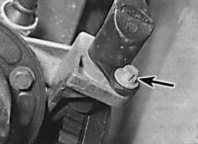
3. Unscrew the bolt (indicated by the arrow) and remove the sensor.
4. Installation is carried out in the reverse order of removal.
5. Using a feeler gauge blade, check that the gap between the end of the sensor and the teeth of the crankshaft pulley is 1±0.7 mm.
Knock sensor
The knock sensor is mounted on the rear of the cylinder block and is accessible from underneath the vehicle.
Removal and installation
1. The knock sensor is mounted on the rear of the engine block and is accessible from underneath the vehicle. Raise the front of the vehicle and support it on stands.
2. Disconnect the sensor electrical connector located on the sensor wires.
3. Unscrew the bolt and remove the sensor from the engine.
4. Check that the mating surfaces of the sensor and the cylinder block are clean and dry, install the sensor, secure it with a bolt and connect the electrical connector.
Electronic control unit (ecu)
The ECU is located under the water deflector in front of the windshield.
Removal and installation
1. Remove the ground cable from the battery. Remove the wiper arms.
2. Remove the upper seal from the engine compartment bulkhead and remove the water deflector.
3. Unscrew the nuts and remove the protective cover of the ECU unit.
4. Disconnect the electrical connectors, unscrew the nuts and remove the ECU unit.
5. Installation is carried out in the reverse order of removal.
Fuel pump relay
The fuel pump relay is located in the engine compartment in the relay block.
Removal and installation
1. Remove the relay box cover and remove the fuel pump relay which is colored purple.
2. Installation is carried out in the reverse order of removal.
Visitor comments