
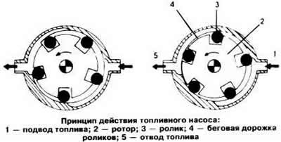
Fuel pump, rotary. Rotor 1 (see picture) pump is eccentrically mounted on the shaft of a permanent magnet motor. In the chambers located around the circumference of the rotor, there are metal rollers 2, which, under the action of centrifugal force, are pressed against the surface of the pump housing, providing a reliable seal. The fuel sucked into the gaps between the rollers and the pump housing is supplied to the discharge pipe 3. With the engine stopped, the check valve 4 closes the fuel supply channel. As soon as the fuel pressure exceeds 4 kg/cm3, the safety valve ball 5 closes the fuel supply channel from the inlet chamber 6.
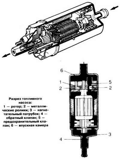
To maintain the required fuel pressure in the system, the fuel pump delivers an amount of fuel that exceeds the fuel consumption of the engine. For example, in full load mode, 70% of the fuel pumped by the pump is drained into the tank after passing through the pressure regulator.
The fuel pump is switched on by a relay that operates at a certain engine speed when the starter is turned on. If the engine is stopped with the ignition on, the power supply circuit of the pump motor is immediately interrupted.
If the engine does not start or starts with difficulty, idles erratically, stalls regardless of the mode of operation, and also does not develop full power, then a fuel pump malfunction may be the cause.
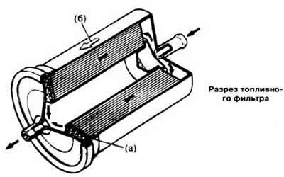
The fuel filter is installed on the delivery pipeline after the fuel pump. A porous paper filter element with a retention capacity of 8-10 microns and a filtering surface of about 3000 cm is placed in the filter housing3. Mesh metal filter «A» (see picture) traps particles of the filter element. Therefore, the filter must be installed strictly in the direction of the arrow «6», showing the direction of fuel flow.
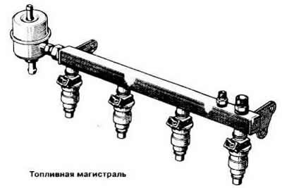
Sockets for injection nozzles are made on the fuel line, and a pressure regulator is installed at its end. The fuel line acts as an accumulator and provides fuel supply under the same pressure to the injectors.
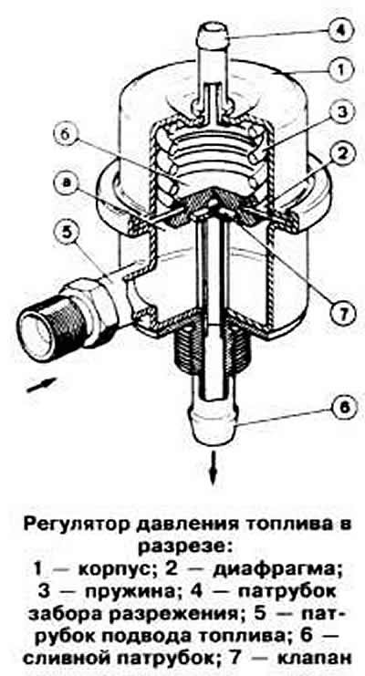
The diaphragm pressure regulator maintains a constant injection pressure regardless of the vacuum in the intake manifold. It consists of a metal case 1 (see picture), diaphragms 2, springs 3, vacuum intake pipe 4 from the inlet pipe, fuel supply pipe 5, drain pipe 6 and valve 7.
If the fuel pressure in the chamber «A» the force of spring 3 becomes greater. valve 7 opens and excess fuel is drained into the tank. Camera «b» connected by a hose to the inlet pipeline, depending on the vacuum in which the spring 3 acts on the valve 7 in such a way that the pressure difference between the chamber «A» and intake piping has always been constant. As a result, regardless of the engine load, the differential pressure supplied to the injectors remains unchanged.
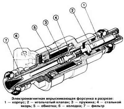
The amount of injected fuel depends only on the duration of the opening of the injectors. determined by the electronic control unit based on information received from the sensors. The composition of the combustible mixture injected into the cylinders is the same, since the nozzles are connected in parallel and open and close at the same time. The injectors inject fuel twice for every revolution of the crankshaft, i.e. at the same time, only half of the amount of fuel required for the working stroke is injected.
Difficult start, inability to start the engine, as well as its unstable idling, indicate a possible malfunction of the injectors.
The air flow meter consists of the following main parts: housing, pressure damper 1 (see picture), compensation damper 2, damper 3, potentiometer 4, intake air temperature sensor 5, bypass channel 6 and quality adjusting screw 7 (composition) mixtures.
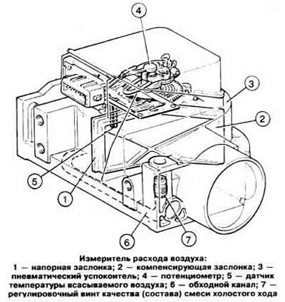
The action of the meter is based on the so-called medium resistance. It measures the force acting on damper 1, which the airflow entering the engine causes to rotate through a certain angle, overcoming the force of the coil spring. The moment of twisting of the spring is chosen so that the damper creates a slight loss of pressure. To prevent swinging of the pressure damper under the influence of fluctuations in the gas flow occurring in the inlet pipeline, there is a pneumatic damper 3, in which a compensation damper 2 is located, having the same working surface as the pressure damper. The volume of the damper, as well as the gap between the compensation damper and the housing, are chosen so that the pressure damper is able to track rapid changes in air flow during acceleration.
A potentiometer connected to the axis of the pressure flap converts the mechanical displacement of the pressure flap into a change in electrical voltage, which is transmitted to the electronic control unit for accurate dosing of fuel. The internal geometry of the meter provides a logarithmic correlation between the air flow and the angular position of the pressure damper. This allows you to accurately calculate the optimal composition of the combustible mixture for non-load engine operation.
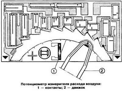
The potentiometer is installed in a sealed housing, from which moisture is completely removed. It consists of a ceramic base with a number of contacts 1 (see picture) and several resistors whose resistance values are corrected by a laser. The resistance of the resistors is constant and does not depend on sudden temperature fluctuations in the engine compartment. The slider 2 is connected to the pressure gate and provides electrical connection with the contacts. To eliminate the effect of battery voltage on the signal produced by the potentiometer, the electronic control unit takes into account the difference between this voltage and the output voltage of the air flow meter.
In parallel with the electrical circuit of the meter, an intake air temperature sensor is connected. It is a resistor with a negative temperature coefficient, i.e. its resistance decreases with increasing temperature. The signals coming from the sensor change the output signal of the meter depending on the temperature of the incoming air. If the engine does not start or starts with difficulty, stalls after starting, if the fuel consumption is too high, and the carbon monoxide content in the exhaust gases is not normal, then a faulty intake air sensor may be the cause.
The bypass channel under the pressure flap is used for the passage of air at idle. Quality (compound) mixture is regulated by changing the flow area of the bypass channel with the adjusting screw 7.
A malfunctioning air flow meter can cause the following engine problems:
- the engine does not start or starts with difficulty;
- the engine starts and stalls;
- the engine is unstable at idle;
- the engine does not have sufficient throttle response;
- increased fuel consumption;
- the engine stalls in all modes;
- the content of carbon monoxide in the exhaust gases does not correspond to the norm;
- the engine does not develop full power.
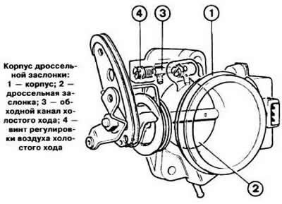
The throttle body consists of the body itself 1 (see picture), throttle valve 2, idle air bypass 3 and idle air adjustment screw 4. The amount of air entering the engine. is determined by the opening of the throttle valve 2, which is mechanically connected to the accelerator pedal. At idle, with the throttle valve closed, the air necessary for the formation of a combustible mixture enters the engine intake channel through the gaps between the edges of the throttle valve and bypass channel 3. The amount of air passing through bypass channel 3, and, therefore, the engine speed at idle speed is adjusted by screw 4.
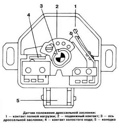
The sensor mounted on the throttle valve shaft has two switching contacts for both end positions of the throttle valve. On center pin 3 (see picture) The sensor has a movable contact 2, which, in accordance with the position of the throttle valve, closes and opens contact 4 at idle or contact 1 at full load. When closed (idling) or wide open throttle (full load) the corresponding signals are sent to the control unit, which, on their basis, stops the generation of injector control pulses or issues commands to enrich the mixture.
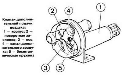
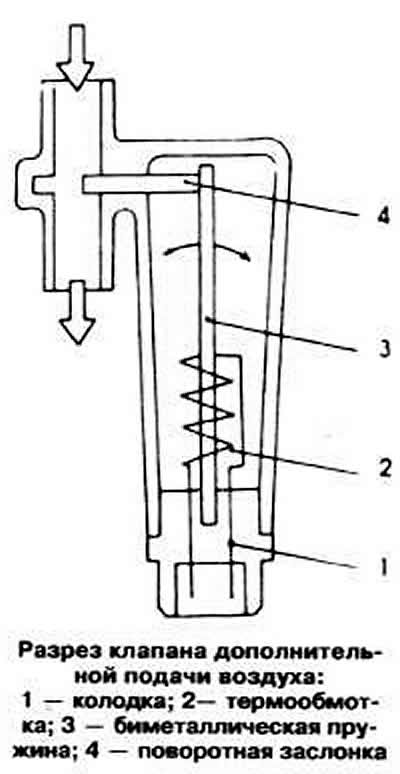
The auxiliary air supply valve is used to increase the engine speed during engine warm-up. It is installed in the air duct, made parallel to the throttle valve, through which the air flow, taken into account by the air flow meter, passes. When starting a cold engine, the additional air supply channel is opened by a rotary valve flap, which moves when the bimetallic spring is heated. As it warms up, the additional air supply channel gradually closes. If the engine does not start or starts with difficulty, stalls after starting, and if the engine speed does not increase as the engine warms up, then this valve may be the cause.
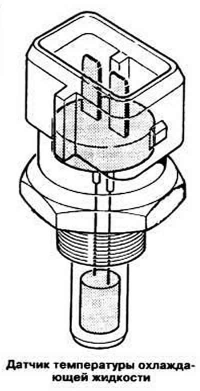
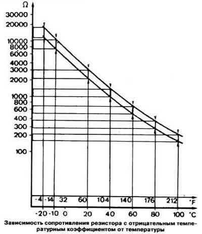
During engine warm-up, the control unit provides enrichment of the combustible mixture based on an electrical signal from the coolant temperature sensor installed in the cylinder head. The sensor is an NTC resistor, i.e. its resistance decreases with increasing temperature (see chart). If the engine does not start or starts with difficulty, stalls after starting, as well as with increased fuel consumption and abnormal CO content in the exhaust gases, it is necessary to check the serviceability of the coolant temperature sensor.
The electronic control unit processes information about the engine operating mode (intake air volume and temperature, engine speed, coolant temperature and load) and converts it into an electronic pulse that determines the moment and duration of the injection. In this case, the duration of the control pulses depends primarily on the amount of incoming air and the engine speed.
With a cold start of the engine and its subsequent warming up, a significant enrichment of the working mixture is necessary. For this purpose, the control unit issues commands to increase the duration of fuel injection by injectors after processing electrical signals from the coolant temperature and intake air temperature sensors.
When the throttle valve is closed, the engine crankshaft rotates at a higher frequency, the control unit stops fuel injection. This is due to considerations of fuel economy and reducing the toxicity of exhaust gases. The generation of injector control pulses stops when the contact closes idle speed of the throttle position sensor (those. with the accelerator pedal released), if the crankshaft speed exceeds the set value. When the engine mode decreases to the value entered in the memory of the control unit, the unit again begins to issue control pulses to the injectors, the duration of which will be determined by the temperature of the coolant. To prevent a sudden change in engine torque, when injection is resumed, the injectors inject fuel in two stages: first, only a small part of the fuel dose is sprayed, and then the rest of the fuel is injected within a few tenths of a second.
Visitor comments