


Contents: Adjusting engine idle speed ⬇ Checking and adjusting the throttle…⬇ Checking the air flow meter ⬇ Checking the fuel supply pressure ⬇ Checking the performance of the fuel…⬇ Checking the fuel pressure regulator ⬇ Checking the coolant temperature…⬇
Warnings.
To check and adjust the injection system "LE-Jetronic" to avoid injury and damage to system components, you must follow these rules.
Do not operate the engine if the wire clamps are not securely fastened to the battery terminals.
Do not disconnect the wires from the battery terminals while the engine is running.
It is necessary to disconnect the battery from the vehicle's electrical system when charging it in a vehicle from an external power source.
Do not start the engine using an external power source with a voltage greater than 12 V.
Do not disconnect the electrical connector of the electronic control unit with the ignition on. Before connecting the plug connectors, make sure there is no damage or oxidation on the contacts of the fork and socket parts, and that the connectors are securely connected. Make sure there is a rubber seal on the pads and a retaining spring. Replace a damaged spring. Before carrying out work on the vehicle using electric welding, including spot welding, disconnect the connector of the electronic control unit.
The electronic control unit will glow if the vehicle is exposed to temperatures above 80°C (for example, before placing a freshly painted car in a drying chamber).
Before checking the compression in the engine cylinders, disconnect the pads from the switch and the injection system control relay to prevent fuel from being supplied to the injection nozzles.
Do not check the wires and their connections with a test lamp.
Do not check for voltage in the circuit "for spark".
Adjusting engine idle speed
Adjustment of the engine idle speed is performed on the engine warmed up to normal operating temperature with the ignition timing correctly set, with a serviceable ignition system, with a clean air filter element, with the throttle valve opening correctly adjusted and with the current consumers switched off.
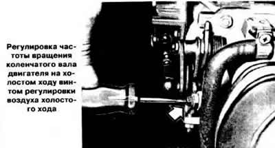
Loosen the lock nut of the idle air adjustment screw located on the throttle body. Turn the screw to set the crankshaft speed within 900-950 rpm on vehicles with a manual transmission and 800-850 rpm on vehicles with an automatic transmission. After adjustment, tighten the lock nut of the adjusting screw.
Connect the gas analyzer according to the instructions.
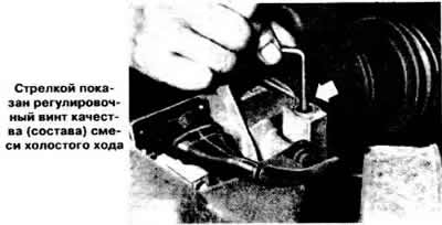
Remove the plug of the mixture quality (composition) adjustment screw located on the air flow meter and, using a socket wrench for screws with an internal recess for a key, turn it until the carbon monoxide (CO) content in the exhaust gases is within 0.2-0.5%. When turning the adjustment screw clockwise, the CO content increases, and vice versa. After completing the adjustment, install a new plug in the air flow meter hole.
Material provided by this website (www.OpelBook.ru)
Checking and adjusting the throttle valve opening
Make sure the throttle valve is closed. Tighten both throttle valve stop screws "B" (see picture) so as to select the gap, then tighten them another ⅛ of a turn.
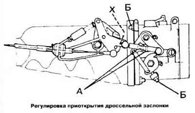
Check the gap "X", which should be equal to 0.5 mm. If the gap does not correspond to this, loosen the lock nut "A" of the connecting rod and adjust the length of the rod until the required gap "X" is obtained. Adjusting the position of the throttle switch
Make sure the throttle opening is adjusted correctly.
Loosen both throttle switch mounting screws (shown by arrows in the figure) and turn the switch housing first clockwise and then carefully in the opposite direction until resistance is felt. In this position, tighten the switch mounting screws.
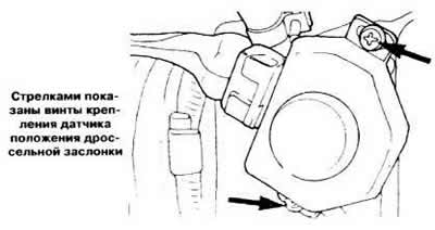
To check the operation of the switch, slightly open the throttle valve: a click should be heard. The same click should be heard when closing the throttle valve.
Checking the air flow meter
Turn off the ignition, disconnect the connector from the electronic control unit, connect an ohmmeter to terminals "8" and "9" of the air flow meter and measure the resistance, which should be within 160-300 Ohms.
Connect an ohmmeter to terminals "7" and "5" of the air flow meter and, moving the pressure flap of the meter with a screwdriver, measure the resistance, which should be within 60-1000 Ohms.
Check the integrity of the circuit by connecting an ohmmeter between the wire coming from terminal "8" of the electronic control unit connector and terminal "8" of the air flow meter. Check the integrity of the circuit by connecting an ohmmeter between the wire coming from terminal "9/3" of the air flow meter and the control unit connector. The ohmmeter readings in both cases should be close to zero.
Check the continuity of the circuit by connecting an ohmmeter between the wire coming from terminal "7" of the control unit connector and terminal "7" of the air flow meter. Check the continuity of the circuit by connecting an ohmmeter between the wire coming from terminal "5/1" of the meter to terminal "5" of the control unit connector. In both cases, the ohmmeter reading should be around 0 ohms.
Checking the fuel supply pressure
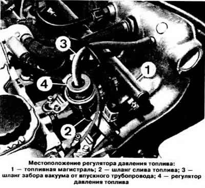
Disconnect the fuel drain hose from the fuel pressure regulator and connect the pressure gauge hose fitting to the pressure regulator hole.
Disconnect the vacuum hose from the fuel pressure regulator and plug the hose hole. Start the engine at idle speed and check the fuel supply pressure on the pressure gauge, which should be within 2.3-2.7 kg/cm².
After checking, connect the fuel drain hose and vacuum hose to the pressure regulator.
Checking the performance of the fuel pump
Disconnect the fuel supply hose from the fuel distribution line and place the end of the hose in a graduated container with a capacity of 5 liters.
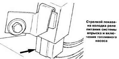
Disconnect the connector of the injection system control relay and fuel pump activation and turn on the pump by short-circuiting terminals "28" and "59" of the block. Check the performance of the fuel pump by measuring the amount of fuel flowing into the vessel, which should be within 0.8-1.0 l/min.
After checking, connect the block to the fuel pump relay and connect the fuel supply hose to the distribution line.
Checking the fuel pressure regulator
Disconnect the fuel supply hose from the pressure regulator and connect the pressure gauge hoses to the fuel supply hose opening and to the regulator nozzle.
Attach the pressure gauge to the fuel supply hose, disconnect the vacuum hose from the fuel pressure regulator.
Start the engine at idle speed and check the nominal control pressure on the pressure gauge, which should be 2.5 kg/cm².
Checking the coolant temperature sensor
Disconnect the connector from the coolant temperature sensor and remove the sensor.
Connect an ohmmeter between terminals "10" and "5" (see picture) sensor.
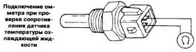
Place the sensor in a tank with water or coolant that can be heated. Turn on the water heating and measure the resistance of the sensor at different temperatures in the tank, which should correspond to the values specified in the subsection "Design and technical characteristics".
Put the sensor in place and connect the connector to it.
Disconnect the connector of the electronic control unit and check the integrity of the circuit by connecting an ohmmeter between the terminal "10" of the block connector block and the terminal "10" of the sensor. The ohmmeter should show a resistance of 0 Ohm.
Check the integrity of the circuit by connecting an ohmmeter between the wire coming from the "33" terminal of the sensor and the "1" plug to the "ground" of the block connector. The ohmmeter should show a resistance of 0 Ohm.
Visitor comments